Controlling Surge & Manual Tuning

I was recently on a service job and watched the tech surge test the compressor.  I’ve seen it done a number of times but for some reason a question came into my mind.

I know the tech is manually manipulating the inlet & bypass valves to increase the unit pressure thus forcing the compressor into a surge condition.  He is listening for the whooshing sound a compressor makes when the max pressure is reached and the air slips into a reverse flow.

The question that hit was how exactly does the controller know when a surge condition has been experienced.  A quick call to my service manager got me the explanation I wanted and I thought you too might benefit from knowing the answer.

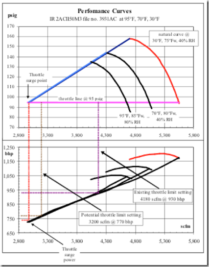
The controller is always looking at the unit pressure.  Not just the final discharge pressure but also the pressure at each stage of compression.  The controller registers a surge when it see a simultaneous drop in pressure and a drop in motor amps.  The controller can register the surge regardless of which stage the pressure drop occurred.  Meaning the surge could have occurred in any stage of the compressor, not just the final stage.

Centrifugal Compressor Flow Curve

Once the controller reaches the pre-set surge count, which is usually programmed by the technician setting up the unit, it pushes the surge line out so the compressor should not reach this point again.  By limiting how far the compressor can go the controller keeps surge from occurring again.

Now that the controller has automatically compensated for the compressor surging we need to further consider: Why did the compressor have a high number of surges?

This could be caused by a number of reasons including compressor component wear.  Perhaps the impeller or diffuser has been worn by particulate or water erosion which now limits the ability of the compressor due to a change in tolerances.  More likely, the cause can be attributed to a change in ambient conditions.  Very likely a temperature change in the air inlet temperature or a change in humidity has occurred or a combination of both.

Further consider that while the controller has modified settings to protect the unit from further surges it has also taken away a potentially useful area of operation.  You see the controller can push the surge line out to prevent further operation within the effected surge area but it will not reverse the line in the opposite direction.  So when ambient conditions again allow compressor operation within the previous zone the controller will not allow operation back within this area without being forced.

To force the controller to allow operation within this zone again a manual tuning must be done to override the controllers automatic pushing of the surge control line.  Think of this as a reset of the controller’s parameters so to speak.

To accomplish this the unit is manually tuned to the proper control set points by a certified technician or knowledgeable operator.

For this reason we recommend manual control tuning be performed at the beginning of each seasonal weather changes.  So as the temperatures begin to rise in the late spring or the temperatures begin to drop in late fall the compressor should be manually tuned by your authorized service company.

When we are selected to provide a preventative maintenance or closed cost service contract we actually retune the compressor each quarter.  If your company is without a contract we recommend at least retuning the compressor twice per year.

As always, if you have any questions, feel free to contact me to discuss further.

Get in Touch

Centrifugal Compressor Controls Tuning

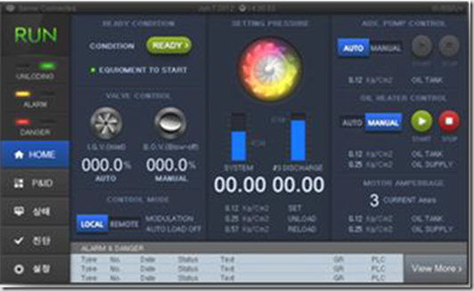
Control Screen

A simple concept of air density is cool air is more dense than warm air.  In a centrifugal compressor application where the flows and pressure are created dynamically the inlet conditions play a major role in the performance of the compressor.

Several factors play a contributing role in the performance including inlet pressure which should remain constant at your physical location.  However, the variable factors include inlet air temperature, humidity and cooling water temperature.

Lower intake air temperatures as well as cooling water temperatures usually go hand in hand.  The lower temperature air will be more dense and will result in higher free air delivery (ACFM) and also higher power consumption of the compressor.

Another factor in air density changes is the available turndown of the compressor.  Meaning the effective flow range through the use of a throttle valve or inlet guide vanes is possible.  A lower temperature inlet air will allow for a wider range of operation in the compressor thus offering a larger amount of turndown.

The lower inlet temperature air also increase the surge pressure!

During the heat of summer the alternate is true where less volume is produced by the compressor and subsequently, less horsepower is used but there may exist an circumstance that the unit will not be able to produce the required plant volume if the unit was not sized appropriately at the onset.

All of this information is critical in initially sizing a dynamic compressors but the point we’re looking to make is the ambient conditions do change the performance of the machine. 

Modern controls are designed to keep the compressor out of surge or choke conditions by moving the surge line to an acceptable position.  However, by moving the surge line the performance of the unit is also altered.

This is the primary reason we suggest re-tuning each centrifugal compressor based on the season.  At least twice per year (as the ambient temperatures increase for summer and decrease for winter) is an ideal time to tune the compressor to achieve peak performance and maximize energy savings.

If your plant has a maintenance contract with a service provider, make sure that tuning the compressor is included twice per year as recommended.  If you perform you own service I would advise contacting a local service company to perform these tuning parameters for your as a one off service.  Typically, tuning controls is outside the expertise of plant maintenance personnel.

Get in Touch

What’s Wrong With My Centrifugal Compressor

Like any piece of mechanical equipment, your centrifugal compressor can experience  problems.

On any given day things are running great and suddenly there is an increase in vibration, The discharge pressure falls or the outlet temperature is too hot.

The question is: What’s wrong.

Thinking Monkey

The simplest solution is to contact your local service professional but sometimes you just want to check it out yourself.  Whether for personal satisfaction or you really need your compressor running in the next few minutes there are always a few simple items you can check and perhaps correct on your own.

We’ve put together a simple list of troubleshooting tips based on potential problems.  Feel free to download the guide which may save you some time in your search.


Click here to reach the troubleshooting guide.

Get in Touch

Inspections & Checklists–Centrifugal Compressor

After learning about all the components in your centrifugal compressor you should now have a comfort level knowing about the parts and operation of your machine. 

To keep your compressor running like new takes time for regular inspections and will also save money on operational cost.  Many of the suggested inspections can be performed by your plant maintenance personnel and keeping detailed records will also help to understand problems as they arise.  At the very least it will be helpful and therefore less costly when your compressed air professional needs to assist with any problems.

Below is a list of typical items you should be reviewing and the suggested frequency that items should be checked.

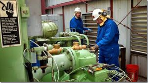
Compressor Tech at work

Scheduled Maintenance Procedures

Daily:

  • Operating data logged during loaded operation and reviewed

Monthly:

  • Inlet air filter elements inspected, (replaced if required)
  • Oil reservoir venting system filter elements inspected, (replaced if required)
  • Compressor bypass valve air supply filter checked (if applicable)
  • Intercooler / aftercooler condensate removal system checked
  • Control system operation checked

Quarterly:

  • Compressor operations data analyzed
  • Main drive motor bearings lubricated per motor manufacturers instructions
  • Condensate traps cleaned and inspected
  • Intercooler, aftercooler, and oil cooler performance verified
  • Lubrication system oil analyzed

6 Month Interval

  • Oil reservoir venting system (air ejector) filter element changed
  • Oil system filter element changed (if required)
  • Lubrication system oil tested and changed, (if required)
  • Oil pump motor lubricated with recommended grease (if required)
  • Coolant and condensate chemically tested
  • Compressor inlet and discharge valves inspected
  • Inlet guide vane assembly drive screw lubricated (if applicable)
  • Bypass valve lubricated (if Required * Note manual recommendations)
  • Bypass valve air supply filter replaced (If applicable)
  • Bypass valve silencer element and gasket replaced
  • Discharge air check valve inspected and tested for free operation
  • Main drive coupling inspected (coupling type dependent – see manual for proper maintenance)
  • Main drive motor maintenance checks completed and correct alignment verified
  • Perform compressor surge test, recorded result and adjust control setpoints

To further assist you with the checks and inspections above you can download this list at the following link: Maintenance Checklist

To assist with your information collection you can find a checklist to download at the following link:

Operator Inspection Checklist

Of course there will always be items that are beyond the scope of your plant personnel.  That’s when its time to call in a professional.  We recommend an annual visit by your selected service company for detailed inspections on your equipment and to handle the more difficult maintenance that typically requires the unit to be dis-assembled to some degree.

Of course that doesn’t mean you should be out in the dark.  You can download a checklist at the link below that helps you know in advance what items (minimum) that your professional technician should be covering and assist you in making sure all items are covered.


Professional Checklist


I hope the above lists and inspections items are helpful as you work to keep your compressed air system in top operating condition. 


Get in Touch

Prepare Your Compressed Air System For Winter: Final Thoughts

We’ve covered several topics on preparing your compressed air system for cold weather and just wanted to leave you with a final thought on the topic today.

Heat Recovery

A great way to save money during the winter months is to capture the heat that your compressor is generating with a heat recovery system.  Up to 90% of the heat generated by the heat of compression can be captured and utilized elsewhere in the plant with just a little planning and investment.  These can include ambient heat for other areas of the plant, pre-heating boiler combustion air and other additional process heating requirements.  Even if the temperature’s can’t be brought up to full operating requirements, utilizing the waste heat from the compressor can cut down on alternate heating costs.

System Preparation

It’s never too early or too late to plan and prepare for temperature changes.  Especially the extremes of winter and summer.  Put the maintenance and planning items on your calendar so you’re not caught off guard by rapidly changing conditions.  Just to be sure you’re aware – follow me on twitter where we always announce when high and low temperature events are expected.


Get in Touch

Prepare Your Compressed Air System For Winter: More Information

We previously discussed winterizing your compressed air system.. Now we  continuing with additional cold weather tips.

Cold Weather Cautions


Be cautious when working in cold weather.  It really can be dangerous!


Weatherizing your compressed air system and facility is an important step when preparing for colder months to make sure your compressor continues operating efficiently.

Take the following steps to ensure your compressed air system and plant are prepared for the cold temperatures.

Repair weather stripping

Check weather stripping and replace areas that are worn. This includes outdoor piping or any equipment in poorly temperature controlled areas.

Inspect drains and air intake filters

Openings that are exposed to outdoor conditions can be problematic. Check your drains  to assure proper operation and be sure to insulate an lines that carry condensation to area’s exposed to potential freezing conditions.  A frozen line does not carry  condensate very far and when it backs up into the compressor, catastrophic failures can occur. 

Also, be sure that intake filters pulling air from the outdoors has proper rain / snow hoods in place. If they are left unprotected, snow or freezing rain can be drawn into the intake of the compressor and this will create a less than ideal situation.

Plan weatherization

Prepare your system biannually. Prepare your system for the high temperatures of summer and the low temperatures of winter each spring and fall. Regular planned maintenance for your compressed air (and other systems)  ensures that nothing is left to chance.

If preparing and maintaining your system seems overwhelming, talk to your compressed air service company. They will be glad to assist in outlining your specific requirements or can develop a maintenance plan to be performed for you with contract specific requirements.


Get in Touch

Control Valves

How do we keep the air flowing where we need it to go?  Control valves!

In a centrifugal compressor the unit is controlled by several valves.

Inlet Valve

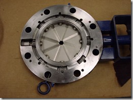
The inlet valve or Inlet Guide Vanes (IGV) controls the amount of air allowed into the 1st stage of compression.  The valve can be as simple as a butterfly valve or more commonly an inlet guide vane which functions as the inlet valve.  The advantage to utilizing the IGV is the incoming air can be pre-swirled to assist in getting the air moving in the correct orientation for the 1st stage impeller to pick up and compress the air.

IGV-closedInlet Guide Vane Valve

Discharge Valve

The discharge air adjust how much air is allowed to leave the compressor and enter the plant piping system.  Personally I prefer the term blow off valve which is simply a valve the blows the compressed air to atmosphere if it is not needed in the plant compressed air piping header.  The most efficient compressors will utilize modulating blow off valves rather than an open/closed arrangement which allows for much finer control of the air that blows off to atmosphere.  It is important to note that the most inefficient aspect of centrifugal compressors is blowing off air that you have just paid money to compressor!

Discharge Check Valve

The discharge check valve is used on the discharge of the compressor to prevent any opportunity for compressed air from the plant header system to backflow into the compressor while it is running unloaded or off.  The backwards flow of air into a centrifugal compressor can spin the impellers in the opposite direction causing massive damage to the unit.

Isolation or Block Valve

A secondary valve on the discharge air line to again prevent any backwards flow of air into the compressor.


All of these valves are controlled by the compressor control system.


Get in Touch

Lubrication System

The previous discussions have focused on a variety of centrifugal components including bearings and gearing.  While a centrifugal compressors meets all of the class requirements for oil free air (just as other types of oil free compressors) there is obviously still a requirement for the bearings and gearing to be lubricated.  The centrifugal compressor maintains it’s oil free status by utilizing seals that keep this oil out of the air stream.

The lubrication system is critical to the longevity of the compressor!  Most centrifugal compressors utilize 2 oil pumps on each compressors.  The primary run oil pump and the auxiliary oil pump.

Prior to compressor startup, the auxiliary oil pump which is electrically driven is started to lubricate the bearings and gears.  The control system monitors the oil pressure and temperature to assure proper levels of each before allowing permission for the unit to be started.

Once the compressor is started the auxiliary oil pump continues to run as the compressor ramps up to full speed.  As the unit begins turning the primary shaft driven oil pump also begins to add oil pressure to the system.  The control system is looking for the additional oil pressure and once this pressure is achieved by both oil pumps running at the same time the control system shuts down the auxiliary oil pump and allows the primary shaft driven oil pump to carry all of the lubrication requirements.

In the event of a shutdown situation, such as a high vibration alarm, high temperature alarm, low oil pressure alarm or any other trip alarm condition the auxiliary oil pump immediately turns back on to assure the unit maintains proper lubrication.

The auxiliary oil pump will also be turned back on when the compressor is put through the shut down sequence.  As the compressor is coasting to a stop, the shaft driven oil pump is not sufficient to provide all of the lubrication so the auxiliary oil pump is used to maintain this lubrication.  Also, once the compressor has stopped it is standard procedure to continue to run the auxiliary oil pump for a period of time to dissipate the heat and cool the gears and bearings.

The lubrication system should also include the following components:

Oil Cooler:

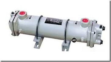
To dissipate the heat from the oil after the oil flow has left the bearing and gear spray area.  The oil is not only used to lubricate the components but also to carry the heat away.  Oil leaving bearings and gear spray areas can be in the 150 degree F range and depending on the manufacturers oil weight requirements, the oil must be cooled to approximately 120 degrees F.  Normally the oil cooler will be a tube in shell design where cooling water flows through the tubes.

Oil Cooler

Oil Filter:

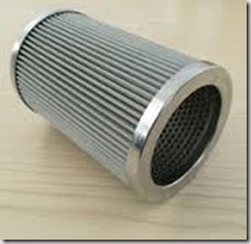
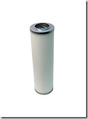
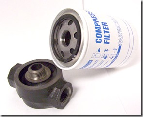
To filter any metal contamination from the oil.  This is the most critical component (IMO) of the lubrication system and I suggest always using an OEM element for the oil filter.  These filters can come in either a spin on design or a cartridge in housing design.  It is frequently recommend to utilize a dual oil filter design such that a filter element can be changed while the compressor remains on line.

imgresOil Filter CartridgeOil Filter Spin On

Oil Mist Collection System:

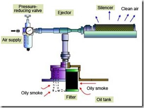
  In all centrifugal compressors, a positive pressure oil mist is created within the gearbox by the meshing gears.  The positive pressure will result in oil leaks through the oil seals if not addressed.  Typically the appropriate action is a simple vacuum venturi  which pulls a vacuum on the oil reservoir to collect the oil mist.  This oil laden air is then passed through a mist eliminator filter to remove the oil mist prior to the air venting to atmosphere.  Most manufacturers also offer an optional electric motor driven vacuum system to eliminate the use of compressed air for this process.

turbo_02

Oil Pressure Regulating Valve:

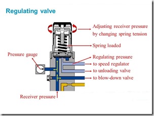
  A simple pressure regulator to assure the proper oil pressure for bearing and gear lubrication.

Oil Pressure Regulating Valve

Temperature Control Valve:

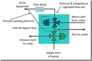
As previously stated, the returning oil (from bearings and gears) is heated and must be cooled via the oil cooler.  To assure oil flowing to bearing and gear spray areas the cool oil is mixed with hot oil to assure the proper temperature.

4504-operation(1)

Routine Operation:

During routine operation, normally a check valve will be used to prevent oil from being pumped back into the reservoir through the auxiliary oil pump.  The pressure regulator is used to maintain proper oil pressure to bearings and gearing and returns any excess oil to the reservoir.

The flow can vary between manufacturers but a possible route is oil being returned from the gears and bearings is directed to the oil cooler and then passes through the oil filter.  The cool, filtered oil is then directed back to the oil reservoir where it is then picked up by the oil pump and directed to the gear sprays, pinion and bull gear bearings.  On some models this same oil is used to lubricate the drive motor bearings.


Get in Touch

Bull Gear: The Driving Force

Our focus has been on the integral geared centrifugal compressor.  This arrangement calls for several pinions shafts (previously discussed) to mounted around a central drive gear, commonly called the Bull Gear.

Bullgear

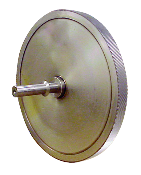
The exploded view of a bull gear (left) shows the helical gearing that will mate with the pinion gear located on the pinion shaft.

Gearbox Gearing Meshimage

The advantage of the integral geared centrifugal is where the bull gear drives multiple pinion shafts, each shaft can be speed altered with simple gear changes.

This arrangement is unlike a barrel type centrifugal compressor where all the stages are driven at the same speed.  This allows each pinion to run at different speeds thus allowing every impeller pair (or single) to operate at it’s optimum aerodynamic speed.  This results in higher efficiencies along with the ability to package the unit in a smaller space.

The bull gear is typically driven by an electric motor at 3600 RPM although various manufacturers may use motors with a rotational speed of 1800 RPM depending on the compressor application.  It should also be noted that in many cases the bull gear can be driven by a steam turbine.  This is a particularly advantageous situation when a large facility has excess steam or the unit can be used as a steam pressure reduction valve (PRV).  In this instance the operational cost of the compressor can be lowered or completely eliminated.


Get in Touch

Keeping Everything In Place: Bearings & Seals

We previously discussed the pinion.  The shaft where the impeller, bearings and seals are mounted prior to the assembly being placed in the gearbox.  As with any rotating equipment, there are mechanical forces seeking to wreak havoc within your centrifugal compressor as well as air and oil flowing throughout the machine.  Today we discuss how everything is held in place with bearings and seals.


Bearings: Radial

There are a couple bearing designs that carry the pinion with the best & most prevalent option being a split, tilt pad bearing.  The multiple pads are free to move about a pivot.  The number of pads & preload can be varied to achieve the desired performance.  The split design allows the bearing to be dis-assembled in the field for inspection and repair.

Image result for split tilt pad bearing

An alternate to the tilt pad bearing is termed a “Hydrostatic squeeze film Babbitt sleeve bearing”.  This bearing is used by a single manufacturer and while the bearing does hold up well in the application it does not maintain the ability to field inspect / repair.  For this reason, this particular manufacturer supplies what is termed a “rotor cartridge”.  This terminology basically means that the pinion is supplied with the bearings, seals and impellers installed and balanced for either placement into a new compressor or to be sent to a client for a repair installation in the field.  While this sounds like a time saving feature for the end user it actually just locks down the client requiring all repairs to be returned to the factory.  While the virtues of this design might be praised by the manufacturer it can be noted that this is NOT the arrangement the manufacturer uses in their custom designed compressors!  If a tilt pad bearing is used on high performance compressors, wouldn’t you prefer this same design to be used on your smaller plant air compressor too?

Bearings: Thrust

Thrust within a centrifugal compressor is a given.  The question is: How is the thrust limited?

For thrust, think of a box fan.  When the fan is running at low speed the box is stable.  However, if the fan speed increases the pressure increases with the air movement from the blades pushing against the static air or perhaps a window screen.  In this circumstance the fan is likely to fall over backwards from the force. 

Image result for box fan falling

This same axial force is present in a centrifugal compressor.  The impeller moving the air forward pushes the pinion shaft in the opposite direction.  Additionally, the helical gearing used for integrally geared compressors create their own axial thrust issues and the force also changes as the load requirements change thus creating a change in the amount of air being pushed through the stage.  As the clearances are extremely tight within the compressor, pinion movement could cause an impact within the compressor and thrust bearings are therefore used to limit this movement.

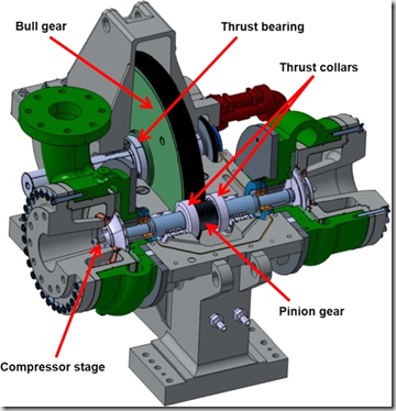
Some manufacturers install bearings on the pinion itself to limit this movement while others use thrust collars to transfer the movement force to the larger bullgear where the thrust load can be taken by much larger thrust bearings.  In my opinion, the larger the surface taking any load, thrust or otherwise, is a better, more reliable option.

Seals

As previously discussed there will be 2 seals on the pinion at each impeller placement.  One being the air seal to eliminate any compressed air leakage and the other to eliminate any oil migration into the air stream.

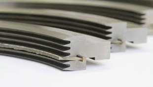
There are 2 basic types of seals used for these applications.  One being a carbon ring seal and the other a labyrinth seal.

The carbon ring type seal physically contacts the shaft to seal either the air in or the oil out.  A drawback to this type seal is the wearing component that contacts the shaft.  As the rings inner bore wears the clearance of the seal opens allowing leakage.  This requires shut down of the compressor for maintenance (replacement) of the seal.

The alternate seal type is a labyrinth seal which provides a tortuous path to prevent air or oil migration.  The biggest advantage of a labyrinth seal is that this type of seal is non-contacting and will not need maintenance (replacement) under normal operating conditions.

imagesImage result for LABYRINTH SEALS

While every component within a centrifugal compressor is crucial, bearings and seals are extremely critical items and care should be taken to make sure you understand how your compressor or a newly proposed compressor operates.  Obviously, the manufacturer’s choice of bearing and seal arrangements are determined by the cost of the arrangement as well as the desired life of the component.  Always have an in depth conversation with your compressed air professional to assure your understanding of your air compressor.


Get in Touch