Rise & Collect

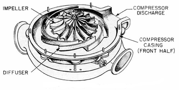
We’ve previously discussed that high velocity air leaving the impeller impacts the blades on the diffuser which slows the air which causes the air pressure to rise.  The next component in a centrifugal compressor is the scroll. Sometimes referred to as the volute.

Scroll 1

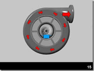
Once the air passes through the diffuser blades it enters the scroll.  As you can see in the above picture, the air passes around the scroll and exits at the top right discharge port.  The air passing through the scroll is further reduced in velocity in which again causes a rise in pressure.

At this point the first stage of compression is finalized resulting in the final pressure from the 1st stage of compression which typically results in a discharge pressure of approximately 14 PSIG on a 100 pound compressor design.  Remember, the aerodynamic engineer can alter the various aspects of the impeller, diffuser and scroll to achieve various outcomes.

It’s also important to note that we likely started with an inlet pressure to the compressor at approximately 14.3 PSIA.  The absolute atmospheric pressure at the location of the compressor.  This location and subsequent absolute pressure are critical considerations for the compressor.  A machine designed for installation at the beach (sea level) with an absolute pressure of 14.7 will not have the same performance if it is moved to a mountain in Denver with an atmospheric pressure of 12 PSIA.

Always assure you’re using the correct readings, whether PSIG or PSIA.  Gauge pressure vs. absolute pressure makes a huge difference.  It’s also interesting to note that most of the work related to pressure increase on a centrifugal compressor is done in subsequent stages.

The secondary function of the scroll is to provide a smooth collection of the air where it will be passed to the next section of the compressor.  The next section could be discharge to the plant, discharge to the next stage of compression or most commonly to a cooler.

 

Get in Touch

Slow The Air Down–Raise The Pressure

We previously discussed how to get the air moving and the role of the impeller in a centrifugal air compressor.  Now that we have air moving at a high rate of speed we need to slow it down.  Slow it down?  Speed up, Slow down – sounds like old people driving on Sunday morning!

I went in search of a great description for today’s topic, the diffuser.  Below is an excerpt from Wikipedia:

As the flow continues into and through the centrifugal impeller, the impeller forces the flow to spin faster and faster. According to a form of Euler‘s fluid dynamics equation, known as pump and turbine equation, the energy input to the fluid is proportional to the flow’s local spinning velocity multiplied by the local impeller tangential velocity.

In many cases the flow leaving centrifugal impeller is near the speed of sound (340 metres/second). The flow then typically flows through a stationary compressor causing it to decelerate. These stationary compressors are actually static guide vanes where energy transformation takes place. As described in Bernoulli’s principle, this reduction in velocity causes the pressure to rise leading to a compressed fluid.

What?

I’m glad you’ve made it to this point.  I’m sure you’re thinking, “Principles & Equations, I just want to know how a centrifugal compressor works?”

Here goes: The next piece of the centrifugal compressor is the diffuser.

Diffuser 1

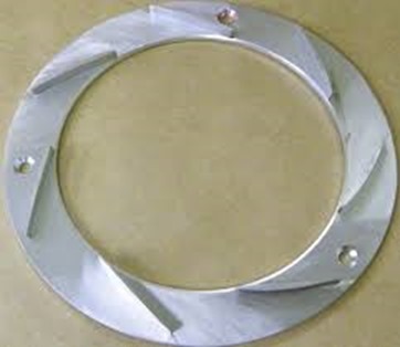
The air leaving the tips of the spinning impeller at high speed now impacts on the stationary diffuser to slow the air down.  By slowing the velocity of the air, a rise in pressure is created.  

Impeller-Diffuser

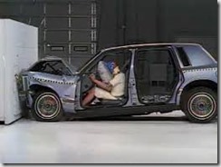
Imagine a car hitting a wall.  Until reaching the wall the car moving with only slight resistance from atmospheric air.  Note that there is some slight pressure against the car at this point which will be important for later discussion’s.  But once it hits the wall the pressure is increased and the increase in pressure collapses the metal of the car.


images

Same thing when the high speed air hits the diffuser.  An increase in pressure, which is what we’re really looking for – compressed air.

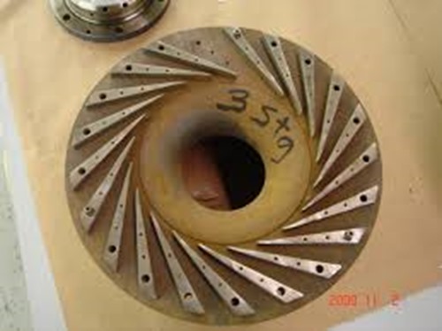
Notice the diffuser below is not just a plain wall.  It has blades on the surface as well.  We don’t really want the air to completely stop (like a car hitting a wall).  We just want to slow it down a bit so the pressure will increase.

Diffuser 3

If you recall discussing the impeller, aerodynamic engineers determine the speed of the impeller along with the length and depth of the impeller blades so the air is moving at the desired velocity.  The same is true with the diffuser.  The engineer determines the number, length and depth of the blades on the diffuser to slow the high speed air to the pre-determined amount to get just the right amount of pressure rise while maintaining the desired flow of air to the next component of the compressor.


Get in Touch

Centrifugal Compressor: Moving The Air

A recent blog post discussed a presentation to a valued client on the topic of centrifugal compressor components, operation, maintenance and troubleshooting.  This client owns and operates 20+ centrifugal compressors ranging from 1000 to 5000 horsepower.  We were surprised to see the number of attendees to the class.  Our thought process was with the number of compressors at this facility, everyone knew everything about centrifugal compressors.  We were wrong.  So you don’t misunderstand, there are lots of capable personnel at the facility but with the constant turnover of position changes, promotions and general churn,  there were plenty that were looking for education.

I surmised that if this plant could use some refresher, then a lot of other people would likely be looking for information as well.  For the next few weeks I’ll be covering some of the items from that presentation.

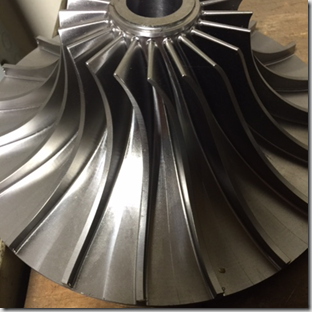
The photo below is the basic component of a centrifugal compressor: The impeller or often called the wheel.

The wheel is the primary rotating component that moves the air.  

Image

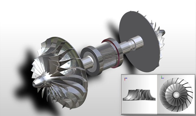
The wheel is mounted on the pinion which lies horizontally in the compressor.  You’ll note that the pinion below has two impellers, one on each end.  This is a common configuration although it is equally common to have only one impeller on a pinion.  

The air enters the impeller at the small end and the vanes grab the air and accelerate it through the vanes to the larger end where it is basically thrown from the fins.  The increasing velocity of the air is the beginning point of how the pressure is increased in a centrifugal compressor.

ImageImpeller Low Profile

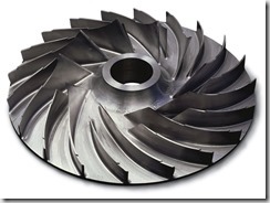
Notice the variation of the blades of the impeller from the two photos above.  The bottom picture shows a much shallower blade as well as the blade being shorter.  The depth, length and angle of the impeller blades is one of the keys to how the aerodynamic engineers achieve various performance from the unit.  The material strength and amount of material is also critical as these impellers can turn up to 70,000 RPM and higher.  Obviously, at these speeds you certainly do not want a blade breaking off which would complete wreck the compressor.

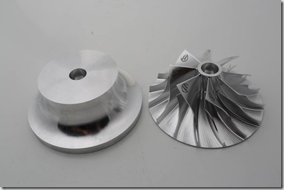
In todays modern engineering and machining world, these impellers are typically cut from a blank stock piece of material using a 5 axis milling machine to achieve the precise characteristics the engineer has determined is required to meet the  performance requested by the end user.  ie: a given flow (ICFM) at a given pressure.   Some manufacturers will create impellers by a casting or forging process although these will result in a less sophisticated component.  The design of the impeller is two-fold, in that it achieves the flow & pressure characteristics required while offer the optimum efficiency for the compressor’s energy requirements.  Again, this is where the best of engineering design creates the most reliable and efficient compressor.

Impeller Blank

The stock material can be of carbon steel, stainless steel or in certain cases, exotic materials depending on the particular gas the unit will be compressing.  Top rated centrifugal compressors for service in compressing air will use stainless steel material rather than carbon steel to achieve longer component life .

Get in Touch