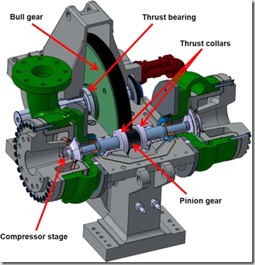
The previous discussions have focused on a variety of centrifugal components including bearings and gearing. While a centrifugal compressors meets all of the class requirements for oil free air (just as other types of oil free compressors) there is obviously still a requirement for the bearings and gearing to be lubricated. The centrifugal compressor maintains it’s oil free status by utilizing seals that keep this oil out of the air stream.
The lubrication system is critical to the longevity of the compressor! Most centrifugal compressors utilize 2 oil pumps on each compressors. The primary run oil pump and the auxiliary oil pump.
Prior to compressor startup, the auxiliary oil pump which is electrically driven is started to lubricate the bearings and gears. The control system monitors the oil pressure and temperature to assure proper levels of each before allowing permission for the unit to be started.
Once the compressor is started the auxiliary oil pump continues to run as the compressor ramps up to full speed. As the unit begins turning the primary shaft driven oil pump also begins to add oil pressure to the system. The control system is looking for the additional oil pressure and once this pressure is achieved by both oil pumps running at the same time the control system shuts down the auxiliary oil pump and allows the primary shaft driven oil pump to carry all of the lubrication requirements.
In the event of a shutdown situation, such as a high vibration alarm, high temperature alarm, low oil pressure alarm or any other trip alarm condition the auxiliary oil pump immediately turns back on to assure the unit maintains proper lubrication.
The auxiliary oil pump will also be turned back on when the compressor is put through the shut down sequence. As the compressor is coasting to a stop, the shaft driven oil pump is not sufficient to provide all of the lubrication so the auxiliary oil pump is used to maintain this lubrication. Also, once the compressor has stopped it is standard procedure to continue to run the auxiliary oil pump for a period of time to dissipate the heat and cool the gears and bearings.
The lubrication system should also include the following components:
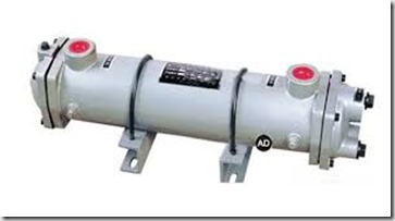
Oil Cooler:
To dissipate the heat from the oil after the oil flow has left the bearing and gear spray area. The oil is not only used to lubricate the components but also to carry the heat away. Oil leaving bearings and gear spray areas can be in the 150 degree F range and depending on the manufacturers oil weight requirements, the oil must be cooled to approximately 120 degrees F. Normally the oil cooler will be a tube in shell design where cooling water flows through the tubes.
Oil Filter:
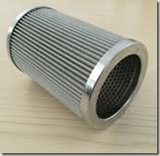
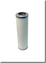
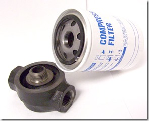
To filter any metal contamination from the oil. This is the most critical component (IMO) of the lubrication system and I suggest always using an OEM element for the oil filter. These filters can come in either a spin on design or a cartridge in housing design. It is frequently recommend to utilize a dual oil filter design such that a filter element can be changed while the compressor remains on line.
Oil Mist Collection System:
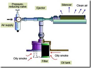
In all centrifugal compressors, a positive pressure oil mist is created within the gearbox by the meshing gears. The positive pressure will result in oil leaks through the oil seals if not addressed. Typically the appropriate action is a simple vacuum venturi which pulls a vacuum on the oil reservoir to collect the oil mist. This oil laden air is then passed through a mist eliminator filter to remove the oil mist prior to the air venting to atmosphere. Most manufacturers also offer an optional electric motor driven vacuum system to eliminate the use of compressed air for this process.
Oil Pressure Regulating Valve:
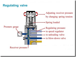
A simple pressure regulator to assure the proper oil pressure for bearing and gear lubrication.
Temperature Control Valve:
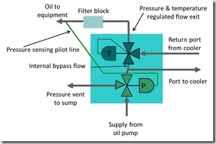
As previously stated, the returning oil (from bearings and gears) is heated and must be cooled via the oil cooler. To assure oil flowing to bearing and gear spray areas the cool oil is mixed with hot oil to assure the proper temperature.
Routine Operation:
During routine operation, normally a check valve will be used to prevent oil from being pumped back into the reservoir through the auxiliary oil pump. The pressure regulator is used to maintain proper oil pressure to bearings and gearing and returns any excess oil to the reservoir.
The flow can vary between manufacturers but a possible route is oil being returned from the gears and bearings is directed to the oil cooler and then passes through the oil filter. The cool, filtered oil is then directed back to the oil reservoir where it is then picked up by the oil pump and directed to the gear sprays, pinion and bull gear bearings. On some models this same oil is used to lubricate the drive motor bearings.


