Keeping Everything In Place: Bearings & Seals

We previously discussed the pinion.  The shaft where the impeller, bearings and seals are mounted prior to the assembly being placed in the gearbox.  As with any rotating equipment, there are mechanical forces seeking to wreak havoc within your centrifugal compressor as well as air and oil flowing throughout the machine.  Today we discuss how everything is held in place with bearings and seals.


Bearings: Radial

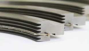
There are a couple bearing designs that carry the pinion with the best & most prevalent option being a split, tilt pad bearing.  The multiple pads are free to move about a pivot.  The number of pads & preload can be varied to achieve the desired performance.  The split design allows the bearing to be dis-assembled in the field for inspection and repair.

Image result for split tilt pad bearing

An alternate to the tilt pad bearing is termed a “Hydrostatic squeeze film Babbitt sleeve bearing”.  This bearing is used by a single manufacturer and while the bearing does hold up well in the application it does not maintain the ability to field inspect / repair.  For this reason, this particular manufacturer supplies what is termed a “rotor cartridge”.  This terminology basically means that the pinion is supplied with the bearings, seals and impellers installed and balanced for either placement into a new compressor or to be sent to a client for a repair installation in the field.  While this sounds like a time saving feature for the end user it actually just locks down the client requiring all repairs to be returned to the factory.  While the virtues of this design might be praised by the manufacturer it can be noted that this is NOT the arrangement the manufacturer uses in their custom designed compressors!  If a tilt pad bearing is used on high performance compressors, wouldn’t you prefer this same design to be used on your smaller plant air compressor too?

Bearings: Thrust

Thrust within a centrifugal compressor is a given.  The question is: How is the thrust limited?

For thrust, think of a box fan.  When the fan is running at low speed the box is stable.  However, if the fan speed increases the pressure increases with the air movement from the blades pushing against the static air or perhaps a window screen.  In this circumstance the fan is likely to fall over backwards from the force. 

Image result for box fan falling

This same axial force is present in a centrifugal compressor.  The impeller moving the air forward pushes the pinion shaft in the opposite direction.  Additionally, the helical gearing used for integrally geared compressors create their own axial thrust issues and the force also changes as the load requirements change thus creating a change in the amount of air being pushed through the stage.  As the clearances are extremely tight within the compressor, pinion movement could cause an impact within the compressor and thrust bearings are therefore used to limit this movement.

Some manufacturers install bearings on the pinion itself to limit this movement while others use thrust collars to transfer the movement force to the larger bullgear where the thrust load can be taken by much larger thrust bearings.  In my opinion, the larger the surface taking any load, thrust or otherwise, is a better, more reliable option.

Seals

As previously discussed there will be 2 seals on the pinion at each impeller placement.  One being the air seal to eliminate any compressed air leakage and the other to eliminate any oil migration into the air stream.

There are 2 basic types of seals used for these applications.  One being a carbon ring seal and the other a labyrinth seal.

The carbon ring type seal physically contacts the shaft to seal either the air in or the oil out.  A drawback to this type seal is the wearing component that contacts the shaft.  As the rings inner bore wears the clearance of the seal opens allowing leakage.  This requires shut down of the compressor for maintenance (replacement) of the seal.

The alternate seal type is a labyrinth seal which provides a tortuous path to prevent air or oil migration.  The biggest advantage of a labyrinth seal is that this type of seal is non-contacting and will not need maintenance (replacement) under normal operating conditions.

imagesImage result for LABYRINTH SEALS

While every component within a centrifugal compressor is crucial, bearings and seals are extremely critical items and care should be taken to make sure you understand how your compressor or a newly proposed compressor operates.  Obviously, the manufacturer’s choice of bearing and seal arrangements are determined by the cost of the arrangement as well as the desired life of the component.  Always have an in depth conversation with your compressed air professional to assure your understanding of your air compressor.

 

Get in Touch

Pinion

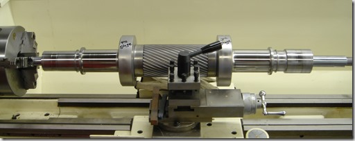
The next component to discuss in the centrifugal compressor is the pinion.  Basically a shaft that carries several key components of the compressor.  Below you can see a photo of a pinion that is set in a lathe for repair but this gives a great view of the bare pinion only. 

JOY - CAMERON PINION


As you can see in the photo, there is a gearing cut in the center of the pinion (shaft) which will be used to rotate the assembly and then on each end of the pinion there are some raised areas and some smooth areas. 

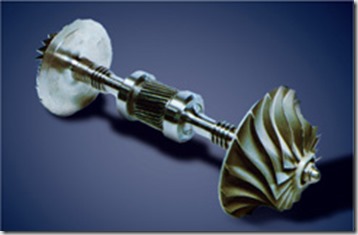
The pinion carries several other key components of the compressor including the impeller or impellers if the pinion is a double hung design as the way pictured.  Below is a photo of a pinion with two impellers mounted.

Pinion assm geared03

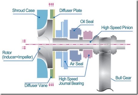
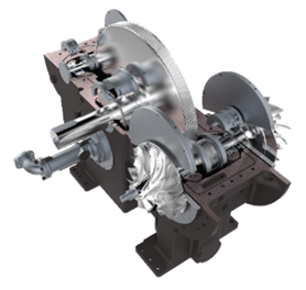
The photo below demonstrates a layout of the various other components mounted on the pinion.

Pinion Assembly with seals-Bearings

As the photo shows, in addition to the impeller on the left end of the shaft; moving to the right you can next see the air seal is shown followed by the oil seal and finally the high speed bearing that carries the weight of the impeller.  Moving down the pinion you can see where the bullgear meshes with the gearing on the pinion.  This gearing will be discussed at a later time as well as the seals and bearings.

Not shown, there would be at a minimum another bearing to the right of the bullgear so that the 2 bearings are completely supporting the entire pinion assembly. 

FYI, the term pinion assembly or rotating assembly or cartridge assembly are all terms used which simply mean the entire rotating assembly which would include the pinion, impeller, bearings and seals.

If this happens to be a double pinion design, then the entire arrangement would be duplicated on the right side of the pinion shaft past the bullgear which would include another bearing (already mentioned), another oil seal, air seal and impeller.

Get in Touch

Cool The Air

We’ve discussed how the air is compressed through each component in a centrifugal compressor.  Now that the air/gas has been compressed in the 1st stage, it has an elevated temperature.  An example on a 400 HP machine with the air inlet temperature at 75 degrees F. the air temperature as it exits the 1st stage is approximately 242 degrees F.

As previously discussed, the ability of the compressor to meet the required performance is based on inlet pressure, inlet temperature and humidity levels.  With cooler air being more dense it is also more easily compressed.  Since the air leaving our 1st stage is at 242 degrees, we need to cool the air down before we move it to the 2nd stage of compression.

Enter the cooler, the next component of discussion in our centrifugal compressor.  Unless, there is a very specialized application the manufacturer will supply a cooler between each stage of compression and a final cooler (after-cooler) after the final stage of compression to cool the air prior to the next stage of compression or enter the plant distribution system.

Normally on compressors as large as centrifugals the cooling medium will be water although some manufacturers do provide air to air coolers up to certain horsepower machines.

imgres

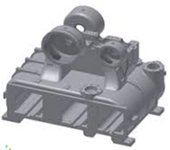
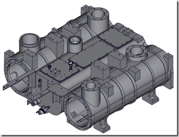
The photo above is a fairly normal centrifugal compressor gearbox and cooler casting.  This is the base building block of the compressor.  The 3 square holes near the bottom of the casting is where the 2 intercoolers and single aftercooler will be located.  the circular holes toward the top are where the impellers and diffusers will reside and the scroll will be mounted to the outside of the circular holes once the impeller and diffuser are mounted.

Remember I stated this is a fairly typical gearbox/cooler casting.  Manufacturers will incorporate a single casting design which can be utilized for several HP sizes.  This saves the manufacturer money rather then a casting design for each single HP compressors. 

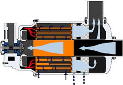
Other designs can be found as well.  One design is shown below where the cooler or cooling tubes surround the inlet air path.  As you can see the air is being drawn down the center toward the impeller.  The air exits the impeller/diffuser to each side where it then channels back through the cooler.  The main issue with this design is the difficulty in disassembly to make any repairs unlike the casting design shown above where the coolers can be independently & easily removed.

images(1)

Best in class design can accomplish even more.  You can see in the photos below that certain manufacturers create separate gearbox and cooler housing castings.  The thought process here is that the gearbox can still be usable for a range of HP sizes but the cooler sizing type can also be customized.  By bolting the gearbox casting to the  cooler casting you complete the casting assembly.  In the event a client needs special large or smaller coolers or perhaps the client needs an API compressor then the gearbox casting and cooler requirements can be totally customized.

ImageImage(1)

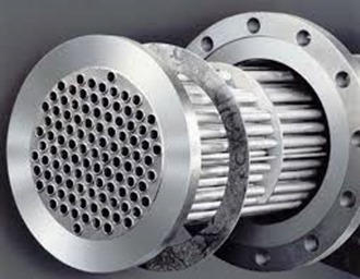
Moving on to the actual working of the cooler.  The cooler itself contains a series of tubes, the inner portion of the photo below.  Best design has the water flowing through the tubes although certain manufacturers reverse this and have air flowing through the tubes.  The air enters the shell of the cooler and flows by the tubes containing the water.  The air transfers the heat to the cooling water flowing through the tubes and the water then exits the cooler flowing back to a cooling tower, chiller or in rare cases a drain if the plant is using city water with a once through design.  (A very expensive alternate)  Most often the tubes are also surrounded by fins which aides in the heat transfer process.

images(2)

A few other items that are important to note:

The tubes in the cooler can be either straight or U-Tubes.  A straight tube design has the water entering one end of the tube, flow straight through to the other end where it exits the cooler assembly.  A U-tube design (cheaper) has the water enter one end of the tube, flows to the opposite end of the cooler where the tubes bends 90 degrees and flows the water back to the originating end of the cooler where it exits.  A U-tube cooler can only be chemically cleaned!  A straight tube design offers the ability to remove both end caps and be mechanically rodded for cleaning.  Please allocate the extra money (if required) and specify straight tube coolers!

The tubes and fins can be made of special materials depending on the service of the machine.  Normal material of construction is copper tubes and aluminum fins.

You will normally hear of coolers being rated in approach temperature such as a 10 degree approach or a 15 degree approach.  This simply means that the air leaving the cooler will be X degrees higher than the cooling medium – in our case normally water.  Where X is the approach rating.  So if a cooler is rated at a 10 degree approach and we have 80 degree water, the air leaving the cooler will be 90 degrees.

So now we’ve cooled the air down to an acceptable temperature for use in the next phase – either the next stage of compression or plant use.

If you read my dryer series you might remember when you have hot air and then cool it down you also condense water.  The same thing just happened in the inter or after cooler.  We had hot air (which is capable of holding large amounts of water vapor) and cooled it down so the water vapor condenses changing it to a liquid state.  Now we certainly do not want liquid water going downstream to our plant and we REALLY do not want liquid water going into our next impeller!  Therefore the design of the cooler casting must be such that the liquid water drops out of the air stream to a low collection point where an automatic drain valve will disperse the water to a drain outside the cooler casting.

A final note on condensate.  We’re discussing water & metals which equals corrosion over a period of time.  Air passages can be sprayed with an anti-corrosion coating for additional protection.  Some manufacturers charge extra for this item and some provide it as standard.  Yes, coating also wear away but any additional protection from corrosion is a good thing!  Remember, your impellers are spinning at high speeds (up to 100, 000 RPM) with very close tolerances.  A piece of rust slag hitting an impeller is not a good idea!

Get in Touch