Prepare Your Compressed Air System For Winter: Final Thoughts

We’ve covered several topics on preparing your compressed air system for cold weather and just wanted to leave you with a final thought on the topic today.

Heat Recovery

A great way to save money during the winter months is to capture the heat that your compressor is generating with a heat recovery system.  Up to 90% of the heat generated by the heat of compression can be captured and utilized elsewhere in the plant with just a little planning and investment.  These can include ambient heat for other areas of the plant, pre-heating boiler combustion air and other additional process heating requirements.  Even if the temperature’s can’t be brought up to full operating requirements, utilizing the waste heat from the compressor can cut down on alternate heating costs.

System Preparation

It’s never too early or too late to plan and prepare for temperature changes.  Especially the extremes of winter and summer.  Put the maintenance and planning items on your calendar so you’re not caught off guard by rapidly changing conditions.  Just to be sure you’re aware – follow me on twitter where we always announce when high and low temperature events are expected.


Get in Touch

Prepare Your Compressed Air System For Winter: More Information

We previously discussed winterizing your compressed air system.. Now we  continuing with additional cold weather tips.

Cold Weather Cautions


Be cautious when working in cold weather.  It really can be dangerous!


Weatherizing your compressed air system and facility is an important step when preparing for colder months to make sure your compressor continues operating efficiently.

Take the following steps to ensure your compressed air system and plant are prepared for the cold temperatures.

Repair weather stripping

Check weather stripping and replace areas that are worn. This includes outdoor piping or any equipment in poorly temperature controlled areas.

Inspect drains and air intake filters

Openings that are exposed to outdoor conditions can be problematic. Check your drains  to assure proper operation and be sure to insulate an lines that carry condensation to area’s exposed to potential freezing conditions.  A frozen line does not carry  condensate very far and when it backs up into the compressor, catastrophic failures can occur. 

Also, be sure that intake filters pulling air from the outdoors has proper rain / snow hoods in place. If they are left unprotected, snow or freezing rain can be drawn into the intake of the compressor and this will create a less than ideal situation.

Plan weatherization

Prepare your system biannually. Prepare your system for the high temperatures of summer and the low temperatures of winter each spring and fall. Regular planned maintenance for your compressed air (and other systems)  ensures that nothing is left to chance.

If preparing and maintaining your system seems overwhelming, talk to your compressed air service company. They will be glad to assist in outlining your specific requirements or can develop a maintenance plan to be performed for you with contract specific requirements.


Get in Touch

Bull Gear: The Driving Force

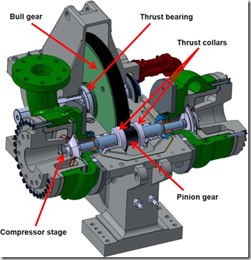
Our focus has been on the integral geared centrifugal compressor.  This arrangement calls for several pinions shafts (previously discussed) to mounted around a central drive gear, commonly called the Bull Gear.

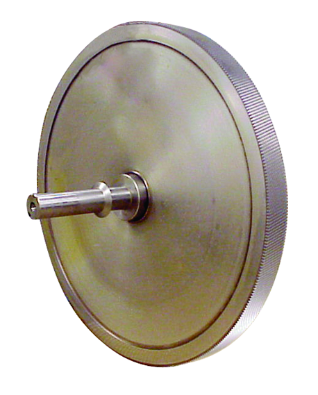
Bullgear

The exploded view of a bull gear (left) shows the helical gearing that will mate with the pinion gear located on the pinion shaft.

Gearbox Gearing Meshimage

The advantage of the integral geared centrifugal is where the bull gear drives multiple pinion shafts, each shaft can be speed altered with simple gear changes.

This arrangement is unlike a barrel type centrifugal compressor where all the stages are driven at the same speed.  This allows each pinion to run at different speeds thus allowing every impeller pair (or single) to operate at it’s optimum aerodynamic speed.  This results in higher efficiencies along with the ability to package the unit in a smaller space.

The bull gear is typically driven by an electric motor at 3600 RPM although various manufacturers may use motors with a rotational speed of 1800 RPM depending on the compressor application.  It should also be noted that in many cases the bull gear can be driven by a steam turbine.  This is a particularly advantageous situation when a large facility has excess steam or the unit can be used as a steam pressure reduction valve (PRV).  In this instance the operational cost of the compressor can be lowered or completely eliminated.


Get in Touch

Keeping Everything In Place: Bearings & Seals

We previously discussed the pinion.  The shaft where the impeller, bearings and seals are mounted prior to the assembly being placed in the gearbox.  As with any rotating equipment, there are mechanical forces seeking to wreak havoc within your centrifugal compressor as well as air and oil flowing throughout the machine.  Today we discuss how everything is held in place with bearings and seals.


Bearings: Radial

There are a couple bearing designs that carry the pinion with the best & most prevalent option being a split, tilt pad bearing.  The multiple pads are free to move about a pivot.  The number of pads & preload can be varied to achieve the desired performance.  The split design allows the bearing to be dis-assembled in the field for inspection and repair.

Image result for split tilt pad bearing

An alternate to the tilt pad bearing is termed a “Hydrostatic squeeze film Babbitt sleeve bearing”.  This bearing is used by a single manufacturer and while the bearing does hold up well in the application it does not maintain the ability to field inspect / repair.  For this reason, this particular manufacturer supplies what is termed a “rotor cartridge”.  This terminology basically means that the pinion is supplied with the bearings, seals and impellers installed and balanced for either placement into a new compressor or to be sent to a client for a repair installation in the field.  While this sounds like a time saving feature for the end user it actually just locks down the client requiring all repairs to be returned to the factory.  While the virtues of this design might be praised by the manufacturer it can be noted that this is NOT the arrangement the manufacturer uses in their custom designed compressors!  If a tilt pad bearing is used on high performance compressors, wouldn’t you prefer this same design to be used on your smaller plant air compressor too?

Bearings: Thrust

Thrust within a centrifugal compressor is a given.  The question is: How is the thrust limited?

For thrust, think of a box fan.  When the fan is running at low speed the box is stable.  However, if the fan speed increases the pressure increases with the air movement from the blades pushing against the static air or perhaps a window screen.  In this circumstance the fan is likely to fall over backwards from the force. 

Image result for box fan falling

This same axial force is present in a centrifugal compressor.  The impeller moving the air forward pushes the pinion shaft in the opposite direction.  Additionally, the helical gearing used for integrally geared compressors create their own axial thrust issues and the force also changes as the load requirements change thus creating a change in the amount of air being pushed through the stage.  As the clearances are extremely tight within the compressor, pinion movement could cause an impact within the compressor and thrust bearings are therefore used to limit this movement.

Some manufacturers install bearings on the pinion itself to limit this movement while others use thrust collars to transfer the movement force to the larger bullgear where the thrust load can be taken by much larger thrust bearings.  In my opinion, the larger the surface taking any load, thrust or otherwise, is a better, more reliable option.

Seals

As previously discussed there will be 2 seals on the pinion at each impeller placement.  One being the air seal to eliminate any compressed air leakage and the other to eliminate any oil migration into the air stream.

There are 2 basic types of seals used for these applications.  One being a carbon ring seal and the other a labyrinth seal.

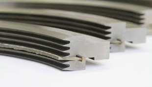
The carbon ring type seal physically contacts the shaft to seal either the air in or the oil out.  A drawback to this type seal is the wearing component that contacts the shaft.  As the rings inner bore wears the clearance of the seal opens allowing leakage.  This requires shut down of the compressor for maintenance (replacement) of the seal.

The alternate seal type is a labyrinth seal which provides a tortuous path to prevent air or oil migration.  The biggest advantage of a labyrinth seal is that this type of seal is non-contacting and will not need maintenance (replacement) under normal operating conditions.

imagesImage result for LABYRINTH SEALS

While every component within a centrifugal compressor is crucial, bearings and seals are extremely critical items and care should be taken to make sure you understand how your compressor or a newly proposed compressor operates.  Obviously, the manufacturer’s choice of bearing and seal arrangements are determined by the cost of the arrangement as well as the desired life of the component.  Always have an in depth conversation with your compressed air professional to assure your understanding of your air compressor.


Get in Touch

Pinion

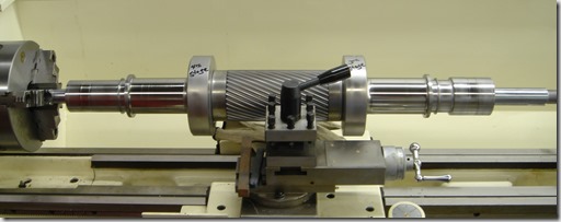
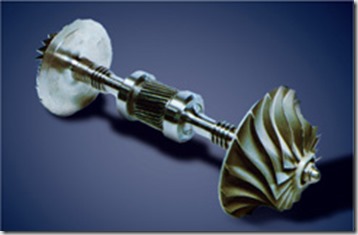
The next component to discuss in the centrifugal compressor is the pinion.  Basically a shaft that carries several key components of the compressor.  Below you can see a photo of a pinion that is set in a lathe for repair but this gives a great view of the bare pinion only. 

JOY - CAMERON PINION


As you can see in the photo, there is a gearing cut in the center of the pinion (shaft) which will be used to rotate the assembly and then on each end of the pinion there are some raised areas and some smooth areas. 

The pinion carries several other key components of the compressor including the impeller or impellers if the pinion is a double hung design as the way pictured.  Below is a photo of a pinion with two impellers mounted.

Pinion assm geared03

The photo below demonstrates a layout of the various other components mounted on the pinion.

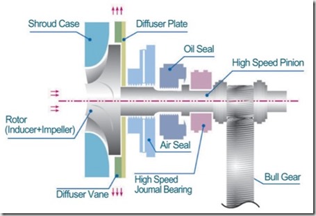
Pinion Assembly with seals-Bearings

As the photo shows, in addition to the impeller on the left end of the shaft; moving to the right you can next see the air seal is shown followed by the oil seal and finally the high speed bearing that carries the weight of the impeller.  Moving down the pinion you can see where the bullgear meshes with the gearing on the pinion.  This gearing will be discussed at a later time as well as the seals and bearings.

Not shown, there would be at a minimum another bearing to the right of the bullgear so that the 2 bearings are completely supporting the entire pinion assembly. 

FYI, the term pinion assembly or rotating assembly or cartridge assembly are all terms used which simply mean the entire rotating assembly which would include the pinion, impeller, bearings and seals.

If this happens to be a double pinion design, then the entire arrangement would be duplicated on the right side of the pinion shaft past the bullgear which would include another bearing (already mentioned), another oil seal, air seal and impeller.

Get in Touch

Cool The Air

We’ve discussed how the air is compressed through each component in a centrifugal compressor.  Now that the air/gas has been compressed in the 1st stage, it has an elevated temperature.  An example on a 400 HP machine with the air inlet temperature at 75 degrees F. the air temperature as it exits the 1st stage is approximately 242 degrees F.

As previously discussed, the ability of the compressor to meet the required performance is based on inlet pressure, inlet temperature and humidity levels.  With cooler air being more dense it is also more easily compressed.  Since the air leaving our 1st stage is at 242 degrees, we need to cool the air down before we move it to the 2nd stage of compression.

Enter the cooler, the next component of discussion in our centrifugal compressor.  Unless, there is a very specialized application the manufacturer will supply a cooler between each stage of compression and a final cooler (after-cooler) after the final stage of compression to cool the air prior to the next stage of compression or enter the plant distribution system.

Normally on compressors as large as centrifugals the cooling medium will be water although some manufacturers do provide air to air coolers up to certain horsepower machines.
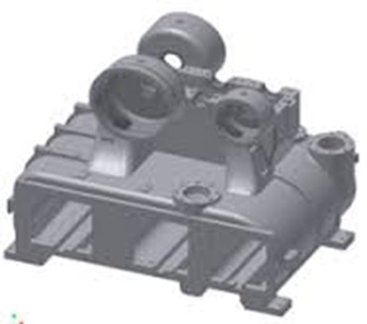
imgres

The photo above is a fairly normal centrifugal compressor gearbox and cooler casting.  This is the base building block of the compressor.  The 3 square holes near the bottom of the casting is where the 2 intercoolers and single aftercooler will be located.  the circular holes toward the top are where the impellers and diffusers will reside and the scroll will be mounted to the outside of the circular holes once the impeller and diffuser are mounted.

Remember I stated this is a fairly typical gearbox/cooler casting.  Manufacturers will incorporate a single casting design which can be utilized for several HP sizes.  This saves the manufacturer money rather then a casting design for each single HP compressors. 

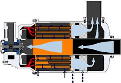
Other designs can be found as well.  One design is shown below where the cooler or cooling tubes surround the inlet air path.  As you can see the air is being drawn down the center toward the impeller.  The air exits the impeller/diffuser to each side where it then channels back through the cooler.  The main issue with this design is the difficulty in disassembly to make any repairs unlike the casting design shown above where the coolers can be independently & easily removed.
images(1)

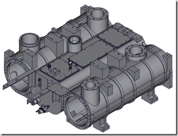
Best in class design can accomplish even more.  You can see in the photos below that certain manufacturers create separate gearbox and cooler housing castings.  The thought process here is that the gearbox can still be usable for a range of HP sizes but the cooler sizing type can also be customized.  By bolting the gearbox casting to the  cooler casting you complete the casting assembly.  In the event a client needs special large or smaller coolers or perhaps the client needs an API compressor then the gearbox casting and cooler requirements can be totally customized.
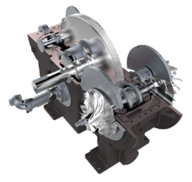
ImageImage(1)

Moving on to the actual working of the cooler.  The cooler itself contains a series of tubes, the inner portion of the photo below.  Best design has the water flowing through the tubes although certain manufacturers reverse this and have air flowing through the tubes.  The air enters the shell of the cooler and flows by the tubes containing the water.  The air transfers the heat to the cooling water flowing through the tubes and the water then exits the cooler flowing back to a cooling tower, chiller or in rare cases a drain if the plant is using city water with a once through design.  (A very expensive alternate)  Most often the tubes are also surrounded by fins which aides in the heat transfer process.
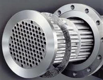
images(2)

A few other items that are important to note:

The tubes in the cooler can be either straight or U-Tubes.  A straight tube design has the water entering one end of the tube, flow straight through to the other end where it exits the cooler assembly.  A U-tube design (cheaper) has the water enter one end of the tube, flows to the opposite end of the cooler where the tubes bends 90 degrees and flows the water back to the originating end of the cooler where it exits.  A U-tube cooler can only be chemically cleaned!  A straight tube design offers the ability to remove both end caps and be mechanically rodded for cleaning.  Please allocate the extra money (if required) and specify straight tube coolers!

The tubes and fins can be made of special materials depending on the service of the machine.  Normal material of construction is copper tubes and aluminum fins.

You will normally hear of coolers being rated in approach temperature such as a 10 degree approach or a 15 degree approach.  This simply means that the air leaving the cooler will be X degrees higher than the cooling medium – in our case normally water.  Where X is the approach rating.  So if a cooler is rated at a 10 degree approach and we have 80 degree water, the air leaving the cooler will be 90 degrees.

So now we’ve cooled the air down to an acceptable temperature for use in the next phase – either the next stage of compression or plant use.

If you read my dryer series you might remember when you have hot air and then cool it down you also condense water.  The same thing just happened in the inter or after cooler.  We had hot air (which is capable of holding large amounts of water vapor) and cooled it down so the water vapor condenses changing it to a liquid state.  Now we certainly do not want liquid water going downstream to our plant and we REALLY do not want liquid water going into our next impeller!  Therefore the design of the cooler casting must be such that the liquid water drops out of the air stream to a low collection point where an automatic drain valve will disperse the water to a drain outside the cooler casting.

A final note on condensate.  We’re discussing water & metals which equals corrosion over a period of time.  Air passages can be sprayed with an anti-corrosion coating for additional protection.  Some manufacturers charge extra for this item and some provide it as standard.  Yes, coating also wear away but any additional protection from corrosion is a good thing!  Remember, your impellers are spinning at high speeds (up to 100, 000 RPM) with very close tolerances.  A piece of rust slag hitting an impeller is not a good idea!

Get in Touch

Slow The Air Down–Raise The Pressure

We previously discussed how to get the air moving and the role of the impeller in a centrifugal air compressor.  Now that we have air moving at a high rate of speed we need to slow it down.  Slow it down?  Speed up, Slow down – sounds like old people driving on Sunday morning!

I went in search of a great description for today’s topic, the diffuser.  Below is an excerpt from Wikipedia:

As the flow continues into and through the centrifugal impeller, the impeller forces the flow to spin faster and faster. According to a form of Euler‘s fluid dynamics equation, known as pump and turbine equation, the energy input to the fluid is proportional to the flow’s local spinning velocity multiplied by the local impeller tangential velocity.

In many cases the flow leaving centrifugal impeller is near the speed of sound (340 metres/second). The flow then typically flows through a stationary compressor causing it to decelerate. These stationary compressors are actually static guide vanes where energy transformation takes place. As described in Bernoulli’s principle, this reduction in velocity causes the pressure to rise leading to a compressed fluid.

What?

I’m glad you’ve made it to this point.  I’m sure you’re thinking, “Principles & Equations, I just want to know how a centrifugal compressor works?”

Here goes: The next piece of the centrifugal compressor is the diffuser.

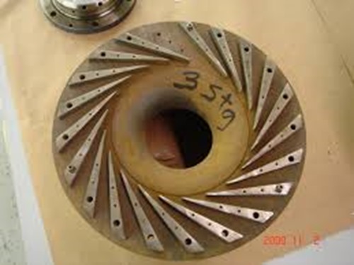
Diffuser 1

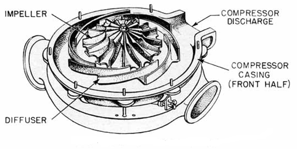
The air leaving the tips of the spinning impeller at high speed now impacts on the stationary diffuser to slow the air down.  By slowing the velocity of the air, a rise in pressure is created.  

Impeller-Diffuser

Imagine a car hitting a wall.  Until reaching the wall the car moving with only slight resistance from atmospheric air.  Note that there is some slight pressure against the car at this point which will be important for later discussion’s.  But once it hits the wall the pressure is increased and the increase in pressure collapses the metal of the car.


images

Same thing when the high speed air hits the diffuser.  An increase in pressure, which is what we’re really looking for – compressed air.

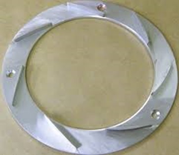
Notice the diffuser below is not just a plain wall.  It has blades on the surface as well.  We don’t really want the air to completely stop (like a car hitting a wall).  We just want to slow it down a bit so the pressure will increase.

Diffuser 3

If you recall discussing the impeller, aerodynamic engineers determine the speed of the impeller along with the length and depth of the impeller blades so the air is moving at the desired velocity.  The same is true with the diffuser.  The engineer determines the number, length and depth of the blades on the diffuser to slow the high speed air to the pre-determined amount to get just the right amount of pressure rise while maintaining the desired flow of air to the next component of the compressor.


Get in Touch

More From Fluid Energy

Last week I announced the new best centrifugal compressor available from Fluid Energy.  This week I want to bring even more from our product line additions. 

Fluid Energy has always been the premier source for centrifugal compressor applications but we want to offer even more.  Being the foremost source for centrifugal compressors allows us a position to help a great number of clients.  Our only apprehension was there remained a great number of clients with smaller oil free compressed requirements that we simply could not assist.  These smaller applications called for a different technology utilizing oil free screw or oil-less scroll compressors.  Over the years Fluid Energy has been approached by a number of manufacturers looking for premier representation of their product line.  Unfortunately, none of these manufacturers met the exacting standards that the Fluid Energy team requires from the products it represents.

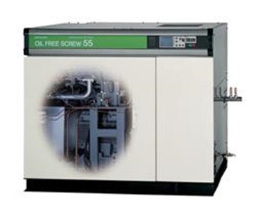
HitachiDSP55a

That Changes Now!

Our distribution agreement with Hitachi positions Fluid Energy to cover ALL of your oil-free compressed air requirements.  Hitachi, being the world leader in oil-free rotary screw  and oil-less scroll compressor technology, lets us assist facilities previously left to less qualified vendors.  Now even the smallest facilities (or small applications within large accounts) can receive the Best-In-Class products and service from Fluid Energy!

The most concerning aspect of oil free rotary screw compressors is the built in failure point – rotor coatings!  With no oil in the compression chamber (air end) to act as a sealing mechanism, the rotors of an oil free rotary screw compressor require a coating to act as a seal thus allowing the intermeshing rotors to compress the air.  As the coating degrades, the efficiency of the air end diminishes and ultimately will no longer compress the air to the design point which requires a costly air end replacement.  A large competitive supplier of oil free rotary screw compressors even states in their operation manual the life expectancy of the air end at 5 years!

Features & Benefits
  • With Hitachi’s patented HX18, Teflon-free coating over their stainless steel rotors our clients can be assured that air end failures from coating degradation are a thing of the past.
  • Hitachi’s two stage air cooling system offers a  patented stainless steel high pre-cooler which eliminates the opportunity for thermal fatigue of the after cooler thus allowing increase efficiency and reliability.
  • The standard equipment “motorized isolation valve” assures moisture causing corrosion is eliminated.
  • The included mist eliminator assures no oil deposits are in the ambient air.
  • ISO class 0 certification
  • With Hitachi US headquarters located in Charlotte, NC along with Fluid Energy’s various Southeast maintenance facilities, replacement parts & service are a quick phone call away.
  • CSG: Customer Satisfaction Guarantee offers a 3 year bumper to bumper warranty including parts & labor with an optional extended air end warranty assure end users their plant will be running at peak efficiency for years to come.
  • Factory Trained and Certified service technicians.

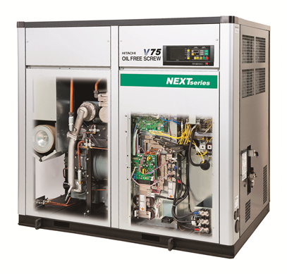
See Inside The Future

DSPV75-NEXT-skeleton (1)

See all the features in the product Video here

Oil-Less Scroll Compressor

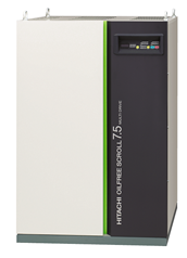
For even smaller applications the Hitachi oil-less scroll compressor is the technology to fit your requirements.  From 2.5 to 44 horsepower utilizing single & multiple head designs we can fit a compressor to your requirements up to 145 psig.  Hitachi actually manufactures the scrolls used on their compressors while the majority of competitors purchase cheaper scroll heads and simply package them on their base.  With only two principal manufacturers of scroll type air compressor heads, wouldn’t you feel more secure knowing the manufacturer of your compressor actually understands the primary component? 

06_SRL-7.5DMPCutaway of SRL

Learn more about Hitachi’s SRL Scroll series in the product Video

Contact us today to learn more about taking your facility to the “Next” level.


Get in Touch

Training Seminar

Training

Over my 30 year career in the compressed air industry I have led countless seminars.  They have varied in topics from general compressors to drying compressed air to control systems and have been presented to engineering firms and a myriad of industrial client types.

I was recently working with an engineer at Eastman Chemical on a water problem he was experiencing in a particular part of the plant.  A few weeks after the conclusion of the evaluation I received an email from him asking if there might be an opportunity for them (he and his team) to attend a factory training seminar with the centrifugal compressor company we represent.  I asked what in particular they had an interest in learning. 

His response was, they would like a presentation on how a centrifugal compressor works, the various components, the control technology and setup along with maintenance recommendations.  I told my client that myself along with Scott Mitchell (our service manager) would be glad to do a seminar for them which would save them any travel cost or charges for having factory personnel come in for training.  He thought this was an excellent idea and we moved forward to add them to the schedule.

To be honest I was somewhat surprised by the request.  I have worked with Eastman for the past 20 years and this is a company that maintains over a dozen centrifugal compressors just for the instrument air system.  The units range from 1000 horsepower up to 5000 horsepower each so they are very well versed in centrifugal compressors.  I surmised that there must be some new folks at the plant that could benefit from the training seminar.

When we arrived for set up I was again surprised to see 15 attendees ranging from hands on maintenance personnel up to Sr. level engineering that I had worked with for years.  I have to admit, knowing the knowledge level in the room made the situation a little intimidating!

A few days after the training seminar I received the email below from my contact that arranged the presentation.


——@eastman.com

On Thu, Apr 28, 2016 at 7:50 AM, ——, Brian –. —— <——-@eastman.com> wrote:

Ken/Scott,

Thanks for your time Tuesday in presenting the material on centrifugal compressors.  You obviously put a lot of time into the slides.  It was a big help to us all, I got a lot of compliments on your presentation.  Maybe we’ll try again one day with a different audience.  Anyway, just wanted to say thank you again from all the folks at Eastman.

Regards,

—– ——

Utilities Division

Distribution Services Dept.

(Printed with permission, names excluded)


If we can make an impact at Eastman Chemical, I hope you will trust us to make an impact at your facility.  Contact me today to discuss your training requirements.


Get in Touch