What’s Wrong With My Centrifugal Compressor

Like any piece of mechanical equipment, your centrifugal compressor can experience  problems.

On any given day things are running great and suddenly there is an increase in vibration, The discharge pressure falls or the outlet temperature is too hot.

The question is: What’s wrong.

Thinking Monkey

The simplest solution is to contact your local service professional but sometimes you just want to check it out yourself.  Whether for personal satisfaction or you really need your compressor running in the next few minutes there are always a few simple items you can check and perhaps correct on your own.

We’ve put together a simple list of troubleshooting tips based on potential problems.  Feel free to download the guide which may save you some time in your search.


Click here to reach the troubleshooting guide.

Get in Touch

Inspections & Checklists–Centrifugal Compressor

After learning about all the components in your centrifugal compressor you should now have a comfort level knowing about the parts and operation of your machine. 

To keep your compressor running like new takes time for regular inspections and will also save money on operational cost.  Many of the suggested inspections can be performed by your plant maintenance personnel and keeping detailed records will also help to understand problems as they arise.  At the very least it will be helpful and therefore less costly when your compressed air professional needs to assist with any problems.

Below is a list of typical items you should be reviewing and the suggested frequency that items should be checked.

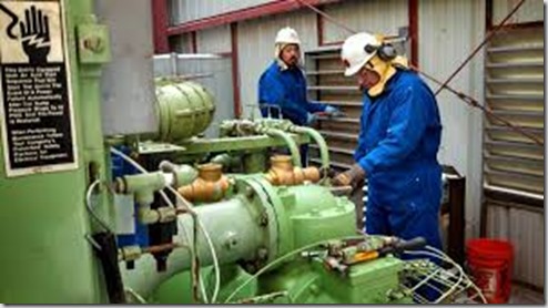
Compressor Tech at work

Scheduled Maintenance Procedures

Daily:

  • Operating data logged during loaded operation and reviewed

Monthly:

  • Inlet air filter elements inspected, (replaced if required)
  • Oil reservoir venting system filter elements inspected, (replaced if required)
  • Compressor bypass valve air supply filter checked (if applicable)
  • Intercooler / aftercooler condensate removal system checked
  • Control system operation checked

Quarterly:

  • Compressor operations data analyzed
  • Main drive motor bearings lubricated per motor manufacturers instructions
  • Condensate traps cleaned and inspected
  • Intercooler, aftercooler, and oil cooler performance verified
  • Lubrication system oil analyzed

6 Month Interval

  • Oil reservoir venting system (air ejector) filter element changed
  • Oil system filter element changed (if required)
  • Lubrication system oil tested and changed, (if required)
  • Oil pump motor lubricated with recommended grease (if required)
  • Coolant and condensate chemically tested
  • Compressor inlet and discharge valves inspected
  • Inlet guide vane assembly drive screw lubricated (if applicable)
  • Bypass valve lubricated (if Required * Note manual recommendations)
  • Bypass valve air supply filter replaced (If applicable)
  • Bypass valve silencer element and gasket replaced
  • Discharge air check valve inspected and tested for free operation
  • Main drive coupling inspected (coupling type dependent – see manual for proper maintenance)
  • Main drive motor maintenance checks completed and correct alignment verified
  • Perform compressor surge test, recorded result and adjust control setpoints

To further assist you with the checks and inspections above you can download this list at the following link: Maintenance Checklist

To assist with your information collection you can find a checklist to download at the following link:

Operator Inspection Checklist

Of course there will always be items that are beyond the scope of your plant personnel.  That’s when its time to call in a professional.  We recommend an annual visit by your selected service company for detailed inspections on your equipment and to handle the more difficult maintenance that typically requires the unit to be dis-assembled to some degree.

Of course that doesn’t mean you should be out in the dark.  You can download a checklist at the link below that helps you know in advance what items (minimum) that your professional technician should be covering and assist you in making sure all items are covered.


Professional Checklist


I hope the above lists and inspections items are helpful as you work to keep your compressed air system in top operating condition. 


Get in Touch

Surge & Choke

In the segment we’ll discuss two critical characteristics of a centrifugal compressor prior to moving into our discussion of the main controller.

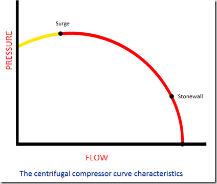
Flow Curve - Basic

Surge

What is surge? 

•Surge is the reversal of flow within a dynamic compression that takes place when the capacity being handled is reduced to a point where insufficient pressure is being generated to maintain flow.

In layman terms, this means that for the flow through the compressor at a given point, the pressure has reached  the maximum limit the impeller of the compressor can push against.  Therefore, since the compressor cannot overcome the pressure, the air flow slips backwards rather than being pushed into the system.

•This condition can potentially damage the compressor if it is severe and is allowed to remain in that state for a prolonged period; therefore, control and prevention is required.

The resulting problem with a surge condition is twofold:

  1. The backward flow of air causes severe vibration within the compressor potentially resulting in damage to internal components.
  2. As air is compressed, heat is generated.  When a surge occurs, the air has been compressed (to a certain point) which has heated the air.  The air then slips backwards on the impeller and will be grabbed at some point by the impeller to be compressed (moved forward in the compression sequence) at which point it is heated again.  As we previously discussed, the temperature of the air moving from stage to stage plays a large part in the design of the entire compressor and at this point we are heating the air above it’s intended design point.

The term surge should also be clarified as the term can have multiple meanings.

Surge Terminology in Centrifugal Compressors:

•Throttle Surge – When flow across the compressor drops till the surge line while maintaining constant pressure.

• To prevent such occurrence, the bypass valve is open before reaching the surge point

• Natural Surge – When pressure reach the maximum the compressor can compress (exceed the physical limitation of the compressor).

•Typically 110% of compressor rated pressure

image

Stonewall

Stonewall is the effect at the opposite side of the curve from the surge point in the chart above.  At some point, as the discharge pressure falls and the airflow through increases at full load, the physical limitations will not allow more air through the stages — this point is known as stonewall. Continued operation at or beyond this point can cause such high flow rates with greater pressure differential that the impellers will not totally fill the vane areas and a cavitation-like action will occur, creating another type of surge with damaging vibrations.


Get in Touch

Control Valves

How do we keep the air flowing where we need it to go?  Control valves!

In a centrifugal compressor the unit is controlled by several valves.

Inlet Valve

The inlet valve or Inlet Guide Vanes (IGV) controls the amount of air allowed into the 1st stage of compression.  The valve can be as simple as a butterfly valve or more commonly an inlet guide vane which functions as the inlet valve.  The advantage to utilizing the IGV is the incoming air can be pre-swirled to assist in getting the air moving in the correct orientation for the 1st stage impeller to pick up and compress the air.

IGV-closedInlet Guide Vane Valve

Discharge Valve

The discharge air adjust how much air is allowed to leave the compressor and enter the plant piping system.  Personally I prefer the term blow off valve which is simply a valve the blows the compressed air to atmosphere if it is not needed in the plant compressed air piping header.  The most efficient compressors will utilize modulating blow off valves rather than an open/closed arrangement which allows for much finer control of the air that blows off to atmosphere.  It is important to note that the most inefficient aspect of centrifugal compressors is blowing off air that you have just paid money to compressor!

Discharge Check Valve

The discharge check valve is used on the discharge of the compressor to prevent any opportunity for compressed air from the plant header system to backflow into the compressor while it is running unloaded or off.  The backwards flow of air into a centrifugal compressor can spin the impellers in the opposite direction causing massive damage to the unit.

Isolation or Block Valve

A secondary valve on the discharge air line to again prevent any backwards flow of air into the compressor.


All of these valves are controlled by the compressor control system.


Get in Touch

Rise & Collect

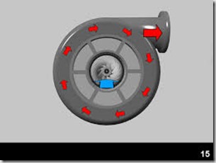
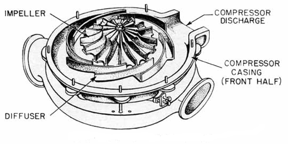
We’ve previously discussed that high velocity air leaving the impeller impacts the blades on the diffuser which slows the air which causes the air pressure to rise.  The next component in a centrifugal compressor is the scroll. Sometimes referred to as the volute.

Scroll 1

Once the air passes through the diffuser blades it enters the scroll.  As you can see in the above picture, the air passes around the scroll and exits at the top right discharge port.  The air passing through the scroll is further reduced in velocity in which again causes a rise in pressure.

At this point the first stage of compression is finalized resulting in the final pressure from the 1st stage of compression which typically results in a discharge pressure of approximately 14 PSIG on a 100 pound compressor design.  Remember, the aerodynamic engineer can alter the various aspects of the impeller, diffuser and scroll to achieve various outcomes.

It’s also important to note that we likely started with an inlet pressure to the compressor at approximately 14.3 PSIA.  The absolute atmospheric pressure at the location of the compressor.  This location and subsequent absolute pressure are critical considerations for the compressor.  A machine designed for installation at the beach (sea level) with an absolute pressure of 14.7 will not have the same performance if it is moved to a mountain in Denver with an atmospheric pressure of 12 PSIA.

Always assure you’re using the correct readings, whether PSIG or PSIA.  Gauge pressure vs. absolute pressure makes a huge difference.  It’s also interesting to note that most of the work related to pressure increase on a centrifugal compressor is done in subsequent stages.

The secondary function of the scroll is to provide a smooth collection of the air where it will be passed to the next section of the compressor.  The next section could be discharge to the plant, discharge to the next stage of compression or most commonly to a cooler.


Get in Touch

Slow The Air Down–Raise The Pressure

We previously discussed how to get the air moving and the role of the impeller in a centrifugal air compressor.  Now that we have air moving at a high rate of speed we need to slow it down.  Slow it down?  Speed up, Slow down – sounds like old people driving on Sunday morning!

I went in search of a great description for today’s topic, the diffuser.  Below is an excerpt from Wikipedia:

As the flow continues into and through the centrifugal impeller, the impeller forces the flow to spin faster and faster. According to a form of Euler‘s fluid dynamics equation, known as pump and turbine equation, the energy input to the fluid is proportional to the flow’s local spinning velocity multiplied by the local impeller tangential velocity.

In many cases the flow leaving centrifugal impeller is near the speed of sound (340 metres/second). The flow then typically flows through a stationary compressor causing it to decelerate. These stationary compressors are actually static guide vanes where energy transformation takes place. As described in Bernoulli’s principle, this reduction in velocity causes the pressure to rise leading to a compressed fluid.

What?

I’m glad you’ve made it to this point.  I’m sure you’re thinking, “Principles & Equations, I just want to know how a centrifugal compressor works?”

Here goes: The next piece of the centrifugal compressor is the diffuser.

Diffuser 1

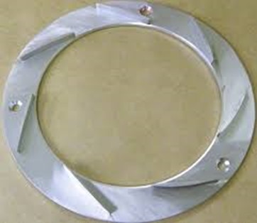
The air leaving the tips of the spinning impeller at high speed now impacts on the stationary diffuser to slow the air down.  By slowing the velocity of the air, a rise in pressure is created.  

Impeller-Diffuser

Imagine a car hitting a wall.  Until reaching the wall the car moving with only slight resistance from atmospheric air.  Note that there is some slight pressure against the car at this point which will be important for later discussion’s.  But once it hits the wall the pressure is increased and the increase in pressure collapses the metal of the car.


images

Same thing when the high speed air hits the diffuser.  An increase in pressure, which is what we’re really looking for – compressed air.

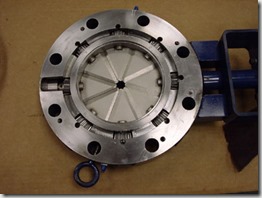
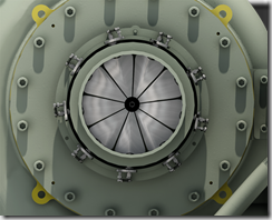
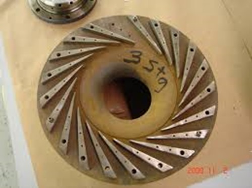
Notice the diffuser below is not just a plain wall.  It has blades on the surface as well.  We don’t really want the air to completely stop (like a car hitting a wall).  We just want to slow it down a bit so the pressure will increase.

Diffuser 3

If you recall discussing the impeller, aerodynamic engineers determine the speed of the impeller along with the length and depth of the impeller blades so the air is moving at the desired velocity.  The same is true with the diffuser.  The engineer determines the number, length and depth of the blades on the diffuser to slow the high speed air to the pre-determined amount to get just the right amount of pressure rise while maintaining the desired flow of air to the next component of the compressor.


Get in Touch

Centrifugal Compressor: Moving The Air

A recent blog post discussed a presentation to a valued client on the topic of centrifugal compressor components, operation, maintenance and troubleshooting.  This client owns and operates 20+ centrifugal compressors ranging from 1000 to 5000 horsepower.  We were surprised to see the number of attendees to the class.  Our thought process was with the number of compressors at this facility, everyone knew everything about centrifugal compressors.  We were wrong.  So you don’t misunderstand, there are lots of capable personnel at the facility but with the constant turnover of position changes, promotions and general churn,  there were plenty that were looking for education.

I surmised that if this plant could use some refresher, then a lot of other people would likely be looking for information as well.  For the next few weeks I’ll be covering some of the items from that presentation.

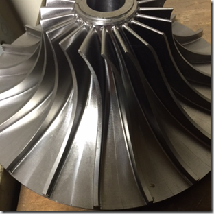
The photo below is the basic component of a centrifugal compressor: The impeller or often called the wheel.

The wheel is the primary rotating component that moves the air.  
Image

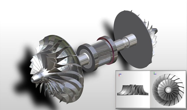
The wheel is mounted on the pinion which lies horizontally in the compressor.  You’ll note that the pinion below has two impellers, one on each end.  This is a common configuration although it is equally common to have only one impeller on a pinion.  

The air enters the impeller at the small end and the vanes grab the air and accelerate it through the vanes to the larger end where it is basically thrown from the fins.  The increasing velocity of the air is the beginning point of how the pressure is increased in a centrifugal compressor.
ImageImpeller Low Profile

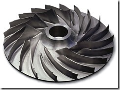
Notice the variation of the blades of the impeller from the two photos above.  The bottom picture shows a much shallower blade as well as the blade being shorter.  The depth, length and angle of the impeller blades is one of the keys to how the aerodynamic engineers achieve various performance from the unit.  The material strength and amount of material is also critical as these impellers can turn up to 70,000 RPM and higher.  Obviously, at these speeds you certainly do not want a blade breaking off which would complete wreck the compressor.

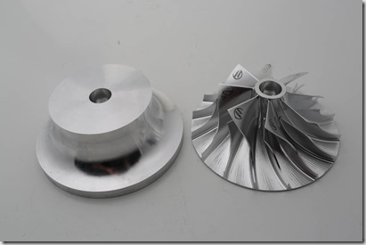
In todays modern engineering and machining world, these impellers are typically cut from a blank stock piece of material using a 5 axis milling machine to achieve the precise characteristics the engineer has determined is required to meet the  performance requested by the end user.  ie: a given flow (ICFM) at a given pressure.   Some manufacturers will create impellers by a casting or forging process although these will result in a less sophisticated component.  The design of the impeller is two-fold, in that it achieves the flow & pressure characteristics required while offer the optimum efficiency for the compressor’s energy requirements.  Again, this is where the best of engineering design creates the most reliable and efficient compressor.
Impeller Blank

The stock material can be of carbon steel, stainless steel or in certain cases, exotic materials depending on the particular gas the unit will be compressing.  Top rated centrifugal compressors for service in compressing air will use stainless steel material rather than carbon steel to achieve longer component life .

Get in Touch