Compressor Performance Comparison

Verification Image

Last week we discussed how air compressors are rated in performance using variations of CFM (Cubic Feet per Minute).

The article discussed keeping the performance stats consistent for comparison.  However, even if various air compressors are listed in the same specification units – how do you know for certain the unit performance you’re being given is an accurate number?

For those of you unfamiliar – enter CAGI.  CAGI stands for compressed air & gas institute.  Reputable manufacturers that offer products within CAGI’s area are members of CAGI.  A great service that CAGI started many years ago is having compressor manufacturers submit compressor performance data to CAGI which is then verified.

With this tool available you can be assured the data you receive is accurate.

You can find the starting point for verification at the following link:

http://www.cagi.org

If you have any question feel free to contact CAGI or myself to discuss.


Get in Touch

Understand The Basics: CFM

Compressed air sign with arrow

Anyone that’s been near an air compressor is familiar with the term CFM.  It’s quite simple and is an acronym for “cubic feet per minute”.  This is a flow measurement based on volume, not weight.

Any cubic foot of air occupies the same space but will have different weights depending on:

Temperature

Humidity

Absolute Pressure


Why is this important?

It’s important to understand to properly match your plant load requirements to your air compressor purchase.  Different manufacturers display their compressor flow data with various terminology.

ICFM – Inlet Cubic Feet per Minute

ICFM is a measurement of the air flow prior to any component of the compression equipment such as an inlet filter (which will cause a drop in pressure)

SCFM – Standard Cubic Feet per Minute

SCFM is a measurement of air flow at an industry standard condition.  That specific condition is normally  stated in the U.S. as 14.696 PSIA (pounds per square inch – absolute), 60 degree F (520 degree R) and 0% relative humidity (RH).

ACFM – Actual Cubic Feet per Minute

ACFM is the actual cubic feet of air that is being delivered from the compression equipment.  If the exact conditions at the compressor location are equal to the SCFM standard conditions then the ACFM would equal the SCFM.  However, this almost never happens!

FAD – Free Air Delivered

FAD is the actual quantity of compressed air converted back to the inlet conditions of the compressor.


The 2 most typical stated flow rates normally seen are ICFM and SCFM.  As long as all the performance data is kept in one type of calculation then comparison of various compressors should work.

However, to assure you are getting a compressor that will actually meet the plant requirements I always ask the client to specify the worst possible operating conditions so compressor performance can be calculated at that point.

If you select a compressor based on SCFM alone then you will not get the stated flow when the summer conditions are 98 degree F ambient and the cooling water is 110 degree F and humidity is 52%.

The flow rates of air compressors is a widely changing variable and many white papers have been written on the subject so end users truly understand what performance they will receive from a specific unit.

We are available to present an entire session on this topic if you would like to completely understand air compressor flow rates.  As a bonus for our readers that are in the engineering discipline, PDH credits can be received for this seminar.

Get in Touch

What’s Wrong With My Centrifugal Compressor

Like any piece of mechanical equipment, your centrifugal compressor can experience  problems.

On any given day things are running great and suddenly there is an increase in vibration, The discharge pressure falls or the outlet temperature is too hot.

The question is: What’s wrong.

Thinking Monkey

The simplest solution is to contact your local service professional but sometimes you just want to check it out yourself.  Whether for personal satisfaction or you really need your compressor running in the next few minutes there are always a few simple items you can check and perhaps correct on your own.

We’ve put together a simple list of troubleshooting tips based on potential problems.  Feel free to download the guide which may save you some time in your search.


Click here to reach the troubleshooting guide.

Get in Touch

Controls

We’ve progressed through the components of a centrifugal compressor.  While the goal is to supply the plant with oil free compressed air, the ideal conditions of supply and demand rarely, if ever, match up.  Meaning the plant use is never matched with the exact output of the compressor.

For that reason a controller is implemented to match the output of the compressor with the needs of the plant.  The controller is responsible for monitoring all of the instrumentation on the compressor such as vibration probes, oil pressure, oil temperature, air temperature both entering the compressor as well as the temperature at the different stages.  This is to assure proper cooling is taking place in the intercoolers.  The controller also typically monitors the pressures at the discharge of each stage to assure the unit is operating at the design point and also measures the motor current.

Turndown

Another important term to understand in the centrifugal compressor world is turndown.  Basically, turndown is the operating range of the compressor between the lines of surge and choke.

image


This gives the end user an understanding of the operating range of the compressor which assists in understanding the efficiency of the unit.  Since the requirements of the plant rarely match the exact output of the compressor we need to know how much the compressors can effectively throttle back to match the plant air requirements.

Control Mode

The controller may normally be set up to control in several different scenario’s.

Constant Pressure:

Constant pressure control is frequently used when system air pressure must be held steady at a specific value or in processes where swings in system pressure is not acceptable.  The inlet valve is modulated to meet the system pressure set point while holding motor current within the Max/Min set points.  In a case of low demand, the compressor will throttle back to the surge control set point.  If demand continues to fall below these set points, the discharge (blowoff) valve will open (modulating if capable) to bypass enough flow to keep the compressor from reaching a surge condition.

Constant Flow

Constant flow control provides a constant flow delivered from the compressor to the system in special applications and works much the way constant pressure controls work.

Auto Dual

Auto Dual control provides efficient compressor operations where some pressure swings are acceptable to the plant.  In Auto Dual mode the compressor controls operate the same as constant pressure until the compressor throttles back to surge control set point.  If demand falls below the throttled condition the controller will unload the compressor.  If the plant requirements increase the compressor will reload to supply air to the plant.  On some models, if the demand remains below this threshold for a set period of time the compressor can be programmed to shutdown and auto restart when system demand requirements rise.

Efficiency Note

The controller for the compressor has a primary function of assuring the compressor meets the demand of the plant air system requirements.  Secondarily, the controller should operate the compressor at peak efficiency in order to keep electrical operating cost to a minimum.  Any time the discharge (blowoff) valve is open, expensive compressed air is being blown off to the atmosphere.  After paying to compressor the air, blowing it to atmosphere is a tremendous waste of resources. 

While most manufacturers offer a variety of interconnected local controllers, Most of these controllers simply do not have the computational power to fully utilize the compressor at peak efficiency.  Regardless of control methods, sophisticated algorithms in central control systems offer faster monitoring & control while utilizing more sophisticated programs.  An example would be where the master controller monitors the rate the system pressure falls to determine the likely time expectancy that the unit will need to reload.

For maximum efficiency it is always recommended to hire a professional compressed air auditing group that maintain engineering personnel dedicated to control systems.

Get in Touch

Wishing Everyone a Joyful Holiday

Merry Christmas & Happy New Year

The lull of the year has arrived.  Hopefully for you that means a peaceful time between Christmas and New Years where we celebrate, spend time with loved one’s and finally get a little downtime.

I just want to take this opportunity to thank all of my clients who have allowed me to work with them, side by side throughout this year to achieve their goals.


Get in Touch

Prepare Your Compressed Air System For Winter: Final Thoughts

We’ve covered several topics on preparing your compressed air system for cold weather and just wanted to leave you with a final thought on the topic today.

Heat Recovery

A great way to save money during the winter months is to capture the heat that your compressor is generating with a heat recovery system.  Up to 90% of the heat generated by the heat of compression can be captured and utilized elsewhere in the plant with just a little planning and investment.  These can include ambient heat for other areas of the plant, pre-heating boiler combustion air and other additional process heating requirements.  Even if the temperature’s can’t be brought up to full operating requirements, utilizing the waste heat from the compressor can cut down on alternate heating costs.

System Preparation

It’s never too early or too late to plan and prepare for temperature changes.  Especially the extremes of winter and summer.  Put the maintenance and planning items on your calendar so you’re not caught off guard by rapidly changing conditions.  Just to be sure you’re aware – follow me on twitter where we always announce when high and low temperature events are expected.


Get in Touch

Prepare Your Compressed Air System For Winter: More Information

We previously discussed winterizing your compressed air system.. Now we  continuing with additional cold weather tips.

Cold Weather Cautions


Be cautious when working in cold weather.  It really can be dangerous!


Weatherizing your compressed air system and facility is an important step when preparing for colder months to make sure your compressor continues operating efficiently.

Take the following steps to ensure your compressed air system and plant are prepared for the cold temperatures.

Repair weather stripping

Check weather stripping and replace areas that are worn. This includes outdoor piping or any equipment in poorly temperature controlled areas.

Inspect drains and air intake filters

Openings that are exposed to outdoor conditions can be problematic. Check your drains  to assure proper operation and be sure to insulate an lines that carry condensation to area’s exposed to potential freezing conditions.  A frozen line does not carry  condensate very far and when it backs up into the compressor, catastrophic failures can occur. 

Also, be sure that intake filters pulling air from the outdoors has proper rain / snow hoods in place. If they are left unprotected, snow or freezing rain can be drawn into the intake of the compressor and this will create a less than ideal situation.

Plan weatherization

Prepare your system biannually. Prepare your system for the high temperatures of summer and the low temperatures of winter each spring and fall. Regular planned maintenance for your compressed air (and other systems)  ensures that nothing is left to chance.

If preparing and maintaining your system seems overwhelming, talk to your compressed air service company. They will be glad to assist in outlining your specific requirements or can develop a maintenance plan to be performed for you with contract specific requirements.


Get in Touch

Winterization

cold-weather-warning

I have a notification system that lets me know when the temperatures are expected to drop below freezing.  Yes, it’s great to know ahead of time so I can plan an indoor day but the real reason for this is to notify my clients through twitter (www.twitter.com/fe_airsystems)

As most already know, compressed air systems can be devastated by freezing temps if your not ready.

When I received my first notice of the season last week I was shocked at far into the year we were.  I  guess it was the extended summer temperatures that caught me off guard and then but I noticed this weekend my area is predicted to see a low temp of 25 degrees.   

I hope you’re keeping track better than me but if not, It’s time to get your compressed air system ready for the cold weather.

This is the first of several posts to help you be cold weather prepared.

Of course maintenance takes place all year long, whether by your own maintenance staff or bringing in your preferred compressed air service specialist but there are a list of additional checks and corrections that need to be made ahead of freezing temperatures.

Check all drains for proper operation

Check drains for obstructions or inefficiencies. If a drain is malfunctioning it can cause serious issues when the temperatures drop. In compressor rooms that are not heated, improperly drained condensate could freeze. If the drain trap is left open, it blows expensive compressed air to the atmosphere and let’s face it – efficiency means everything to companies today.  If not already installed consider adding no air loss type auto drains.  Be sure to inspect drains in the air system equipment, including dyers, receivers and filters.

Maintain air filters

Filters should be checked regularly for clogs or other problems indicated by a high differential pressure. This unnecessary pressure drop can decrease end-use pressure, causing the entire system to work harder and use more energy.  Again, efficiency is king! Coalescing  filter housings partially filled with water are at risk for freeze and rupture event and nobody wants to be around that time bomb.   .

Locate and repair leaks

Leaks can account for up to 25 percent of compressed air use. Identifying and fixing leaks can lead to huge savings. Did I mention efficiency? Some larger leaks can be heard just walking through the area but smaller leaks will require monitoring equipment. You can purchase and utilize an ultrasonic acoustic leak detector or hire a “Quality” compressed air auditing firm.  An auditing company can perform a leak audit only or you can go all out and have them perform a supply & demand side audit to determine additional potential savings for your entire system.

These are the first steps to take when winter is just around the corner.  Follow the blog to learn more pre-cold weather tips.


Get in Touch

Pinion

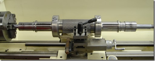
The next component to discuss in the centrifugal compressor is the pinion.  Basically a shaft that carries several key components of the compressor.  Below you can see a photo of a pinion that is set in a lathe for repair but this gives a great view of the bare pinion only. 

JOY - CAMERON PINION


As you can see in the photo, there is a gearing cut in the center of the pinion (shaft) which will be used to rotate the assembly and then on each end of the pinion there are some raised areas and some smooth areas. 

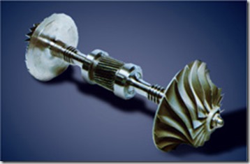
The pinion carries several other key components of the compressor including the impeller or impellers if the pinion is a double hung design as the way pictured.  Below is a photo of a pinion with two impellers mounted.

Pinion assm geared03

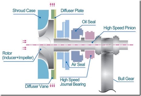
The photo below demonstrates a layout of the various other components mounted on the pinion.

Pinion Assembly with seals-Bearings

As the photo shows, in addition to the impeller on the left end of the shaft; moving to the right you can next see the air seal is shown followed by the oil seal and finally the high speed bearing that carries the weight of the impeller.  Moving down the pinion you can see where the bullgear meshes with the gearing on the pinion.  This gearing will be discussed at a later time as well as the seals and bearings.

Not shown, there would be at a minimum another bearing to the right of the bullgear so that the 2 bearings are completely supporting the entire pinion assembly. 

FYI, the term pinion assembly or rotating assembly or cartridge assembly are all terms used which simply mean the entire rotating assembly which would include the pinion, impeller, bearings and seals.

If this happens to be a double pinion design, then the entire arrangement would be duplicated on the right side of the pinion shaft past the bullgear which would include another bearing (already mentioned), another oil seal, air seal and impeller.

Get in Touch

Cool The Air

We’ve discussed how the air is compressed through each component in a centrifugal compressor.  Now that the air/gas has been compressed in the 1st stage, it has an elevated temperature.  An example on a 400 HP machine with the air inlet temperature at 75 degrees F. the air temperature as it exits the 1st stage is approximately 242 degrees F.

As previously discussed, the ability of the compressor to meet the required performance is based on inlet pressure, inlet temperature and humidity levels.  With cooler air being more dense it is also more easily compressed.  Since the air leaving our 1st stage is at 242 degrees, we need to cool the air down before we move it to the 2nd stage of compression.

Enter the cooler, the next component of discussion in our centrifugal compressor.  Unless, there is a very specialized application the manufacturer will supply a cooler between each stage of compression and a final cooler (after-cooler) after the final stage of compression to cool the air prior to the next stage of compression or enter the plant distribution system.

Normally on compressors as large as centrifugals the cooling medium will be water although some manufacturers do provide air to air coolers up to certain horsepower machines.
imgres

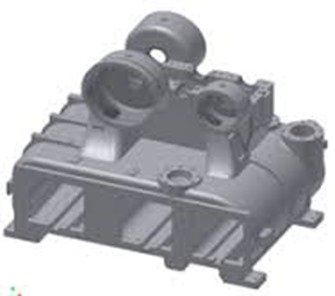
The photo above is a fairly normal centrifugal compressor gearbox and cooler casting.  This is the base building block of the compressor.  The 3 square holes near the bottom of the casting is where the 2 intercoolers and single aftercooler will be located.  the circular holes toward the top are where the impellers and diffusers will reside and the scroll will be mounted to the outside of the circular holes once the impeller and diffuser are mounted.

Remember I stated this is a fairly typical gearbox/cooler casting.  Manufacturers will incorporate a single casting design which can be utilized for several HP sizes.  This saves the manufacturer money rather then a casting design for each single HP compressors. 

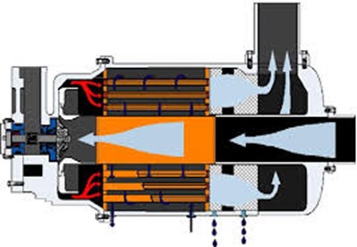
Other designs can be found as well.  One design is shown below where the cooler or cooling tubes surround the inlet air path.  As you can see the air is being drawn down the center toward the impeller.  The air exits the impeller/diffuser to each side where it then channels back through the cooler.  The main issue with this design is the difficulty in disassembly to make any repairs unlike the casting design shown above where the coolers can be independently & easily removed.
images(1)

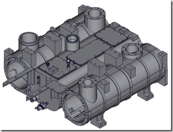
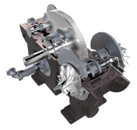
Best in class design can accomplish even more.  You can see in the photos below that certain manufacturers create separate gearbox and cooler housing castings.  The thought process here is that the gearbox can still be usable for a range of HP sizes but the cooler sizing type can also be customized.  By bolting the gearbox casting to the  cooler casting you complete the casting assembly.  In the event a client needs special large or smaller coolers or perhaps the client needs an API compressor then the gearbox casting and cooler requirements can be totally customized.
ImageImage(1)

Moving on to the actual working of the cooler.  The cooler itself contains a series of tubes, the inner portion of the photo below.  Best design has the water flowing through the tubes although certain manufacturers reverse this and have air flowing through the tubes.  The air enters the shell of the cooler and flows by the tubes containing the water.  The air transfers the heat to the cooling water flowing through the tubes and the water then exits the cooler flowing back to a cooling tower, chiller or in rare cases a drain if the plant is using city water with a once through design.  (A very expensive alternate)  Most often the tubes are also surrounded by fins which aides in the heat transfer process.
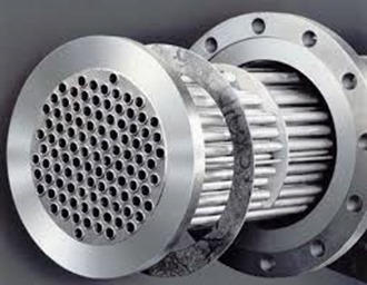
images(2)

A few other items that are important to note:

The tubes in the cooler can be either straight or U-Tubes.  A straight tube design has the water entering one end of the tube, flow straight through to the other end where it exits the cooler assembly.  A U-tube design (cheaper) has the water enter one end of the tube, flows to the opposite end of the cooler where the tubes bends 90 degrees and flows the water back to the originating end of the cooler where it exits.  A U-tube cooler can only be chemically cleaned!  A straight tube design offers the ability to remove both end caps and be mechanically rodded for cleaning.  Please allocate the extra money (if required) and specify straight tube coolers!

The tubes and fins can be made of special materials depending on the service of the machine.  Normal material of construction is copper tubes and aluminum fins.

You will normally hear of coolers being rated in approach temperature such as a 10 degree approach or a 15 degree approach.  This simply means that the air leaving the cooler will be X degrees higher than the cooling medium – in our case normally water.  Where X is the approach rating.  So if a cooler is rated at a 10 degree approach and we have 80 degree water, the air leaving the cooler will be 90 degrees.

So now we’ve cooled the air down to an acceptable temperature for use in the next phase – either the next stage of compression or plant use.

If you read my dryer series you might remember when you have hot air and then cool it down you also condense water.  The same thing just happened in the inter or after cooler.  We had hot air (which is capable of holding large amounts of water vapor) and cooled it down so the water vapor condenses changing it to a liquid state.  Now we certainly do not want liquid water going downstream to our plant and we REALLY do not want liquid water going into our next impeller!  Therefore the design of the cooler casting must be such that the liquid water drops out of the air stream to a low collection point where an automatic drain valve will disperse the water to a drain outside the cooler casting.

A final note on condensate.  We’re discussing water & metals which equals corrosion over a period of time.  Air passages can be sprayed with an anti-corrosion coating for additional protection.  Some manufacturers charge extra for this item and some provide it as standard.  Yes, coating also wear away but any additional protection from corrosion is a good thing!  Remember, your impellers are spinning at high speeds (up to 100, 000 RPM) with very close tolerances.  A piece of rust slag hitting an impeller is not a good idea!

Get in Touch