It seems most every plant I visit has a low pressure problem somewhere in the plant. I’ve written before discussing how pressure flow controllers (PFC) can help with low pressure it certain situations but today I wanted to look at a more common problem. Inadequate pipe size can be a major contributor to low pressure problems in the plant.
Physics dictates that only a certain amount of product, whether it be compressed air, gas or water, will flow through a certain diameter pipe. Also, regardless of the flow being moved the friction of movement causes pressure drop. The more flow that’s attempted to be pushed through the pipe the higher the pressure loss.
I typically see the problem where a plant started with good intentions and design practices but as the plant expands, the main headers and subsequent drop lines are still being used from the original plant air piping system. There is also the case where the original piping was just not large enough to accommodate the flow and the problem gets progressively worse as the years go by.
An often used fix for the problem is to simply set the discharge pressure on the compressor to a higher level which for a period of time will result in a higher pressure reaching the use point. However, as we’ve previously discussed, this solution costs money. Lot’s of money! Therefore the maximum pressure drop should be limited to approximately 1 1/2 PSI between the compressed air system discharge (outlet of the last filter) to the point of use.
The size of the pipe is not the only contributing factor in the plant. Every item within the piping system also plays a very important factor. Consider that each bend (45 or 90 degree) also adds to the limit of the flow through the pipe as well couplings, flex hoses, and quick connects. When all the restrictions are added up it can amaze the end user just how much restriction is in the piping distribution system.
When reviewing the piping system the following items must be taken into account:
- Diameter of pipe
- Length of pipe
- Number of bends couplings (other restrictions)
- SCFM of air required to be passed.
First ,determine the flow from the compressor. This should be a standard rating given by the manufacturer usually in SCFM or Standard Cubic Feet per Minute at a given pressure. It’s wise to note that the SCFM rating by the manufacturer is the flow the compressor can deliver at a standard condition. Meaning the compressor will deliver a given SCFM of air at 68 degree F and 20% relative humidity and if you are reviewing a dynamic compressor, the elevation is also taken into consideration. When any of these parameters are changed then the delivered air by the compressor changes as well.
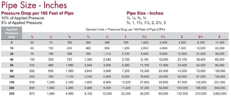
Next, review the chart below, finding your pressure rating in the left hand column and matching it to the pipe size being considered from the top row. The intersection point of these two data items shows the amount of air that can be delivered through the pipe with the stated pressure drop.
Also, remember that the table shows information for straight pipe runs. It does not take bends, couplings, tee’s or other restrictions into account. A pipe with one 90 degree bend will have a greater pressure drop than a straight run of pipe. If the pipe run has 1 bend and 1 tee then the pressure drop will be even higher. The simplest way to add these restrictions to the calculations is to use “equivalent pipe lengths”
The table below shows elbows, Tees, Returns and valves for various size pipe. Adding one of these items equals adding a certain length of pipe to your piping system. For example: adding 1 long radius 90 degree elbow to a 3″ pipe would add a restriction to your piping system that equals 3.4 feet of additional pipe which can be added to the total pipe length in the table above.
Knowing the flow capacity of your compressed air piping distribution system is a critical aspect to achieve maximum efficiency for your system. The slightest change can create a major end result when you’re dealing with thousands of feet of pipe. Even the type of pipe and connections make a difference in flow restrictions.
For new systems where the number of restrictions is unknown, a general rule of thumb is to multiple the total estimated pipe length by 5.5 to estimate for bends, couplings and valves.
When in doubt, it’s always best to consult your compressed air professional for assistance.


