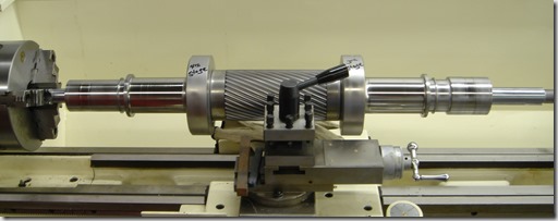
The next component to discuss in the centrifugal compressor is the pinion. Basically a shaft that carries several key components of the compressor. Below you can see a photo of a pinion that is set in a lathe for repair but this gives a great view of the bare pinion only.
As you can see in the photo, there is a gearing cut in the center of the pinion (shaft) which will be used to rotate the assembly and then on each end of the pinion there are some raised areas and some smooth areas.
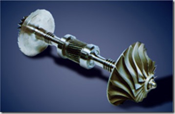
The pinion carries several other key components of the compressor including the impeller or impellers if the pinion is a double hung design as the way pictured. Below is a photo of a pinion with two impellers mounted.
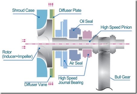
The photo below demonstrates a layout of the various other components mounted on the pinion.
As the photo shows, in addition to the impeller on the left end of the shaft; moving to the right you can next see the air seal is shown followed by the oil seal and finally the high speed bearing that carries the weight of the impeller. Moving down the pinion you can see where the bullgear meshes with the gearing on the pinion. This gearing will be discussed at a later time as well as the seals and bearings.
Not shown, there would be at a minimum another bearing to the right of the bullgear so that the 2 bearings are completely supporting the entire pinion assembly.
FYI, the term pinion assembly or rotating assembly or cartridge assembly are all terms used which simply mean the entire rotating assembly which would include the pinion, impeller, bearings and seals.
If this happens to be a double pinion design, then the entire arrangement would be duplicated on the right side of the pinion shaft past the bullgear which would include another bearing (already mentioned), another oil seal, air seal and impeller.


