A recent blog post discussed a presentation to a valued client on the topic of centrifugal compressor components, operation, maintenance and troubleshooting. This client owns and operates 20+ centrifugal compressors ranging from 1000 to 5000 horsepower. We were surprised to see the number of attendees to the class. Our thought process was with the number of compressors at this facility, everyone knew everything about centrifugal compressors. We were wrong. So you don’t misunderstand, there are lots of capable personnel at the facility but with the constant turnover of position changes, promotions and general churn, there were plenty that were looking for education.
I surmised that if this plant could use some refresher, then a lot of other people would likely be looking for information as well. For the next few weeks I’ll be covering some of the items from that presentation.
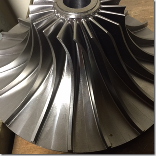
The photo below is the basic component of a centrifugal compressor: The impeller or often called the wheel.
The wheel is the primary rotating component that moves the air.
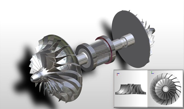
The wheel is mounted on the pinion which lies horizontally in the compressor. You’ll note that the pinion below has two impellers, one on each end. This is a common configuration although it is equally common to have only one impeller on a pinion.
The air enters the impeller at the small end and the vanes grab the air and accelerate it through the vanes to the larger end where it is basically thrown from the fins. The increasing velocity of the air is the beginning point of how the pressure is increased in a centrifugal compressor.
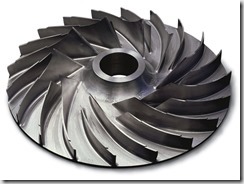
Notice the variation of the blades of the impeller from the two photos above. The bottom picture shows a much shallower blade as well as the blade being shorter. The depth, length and angle of the impeller blades is one of the keys to how the aerodynamic engineers achieve various performance from the unit. The material strength and amount of material is also critical as these impellers can turn up to 70,000 RPM and higher. Obviously, at these speeds you certainly do not want a blade breaking off which would complete wreck the compressor.
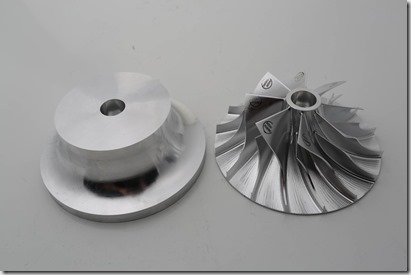
In todays modern engineering and machining world, these impellers are typically cut from a blank stock piece of material using a 5 axis milling machine to achieve the precise characteristics the engineer has determined is required to meet the performance requested by the end user. ie: a given flow (ICFM) at a given pressure. Some manufacturers will create impellers by a casting or forging process although these will result in a less sophisticated component. The design of the impeller is two-fold, in that it achieves the flow & pressure characteristics required while offer the optimum efficiency for the compressor’s energy requirements. Again, this is where the best of engineering design creates the most reliable and efficient compressor.
The stock material can be of carbon steel, stainless steel or in certain cases, exotic materials depending on the particular gas the unit will be compressing. Top rated centrifugal compressors for service in compressing air will use stainless steel material rather than carbon steel to achieve longer component life .


