Controlling Surge & Manual Tuning

I was recently on a service job and watched the tech surge test the compressor.  I’ve seen it done a number of times but for some reason a question came into my mind.

I know the tech is manually manipulating the inlet & bypass valves to increase the unit pressure thus forcing the compressor into a surge condition.  He is listening for the whooshing sound a compressor makes when the max pressure is reached and the air slips into a reverse flow.

The question that hit was how exactly does the controller know when a surge condition has been experienced.  A quick call to my service manager got me the explanation I wanted and I thought you too might benefit from knowing the answer.

The controller is always looking at the unit pressure.  Not just the final discharge pressure but also the pressure at each stage of compression.  The controller registers a surge when it see a simultaneous drop in pressure and a drop in motor amps.  The controller can register the surge regardless of which stage the pressure drop occurred.  Meaning the surge could have occurred in any stage of the compressor, not just the final stage.

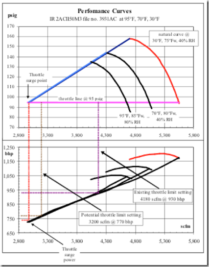
Centrifugal Compressor Flow Curve

Once the controller reaches the pre-set surge count, which is usually programmed by the technician setting up the unit, it pushes the surge line out so the compressor should not reach this point again.  By limiting how far the compressor can go the controller keeps surge from occurring again.

Now that the controller has automatically compensated for the compressor surging we need to further consider: Why did the compressor have a high number of surges?

This could be caused by a number of reasons including compressor component wear.  Perhaps the impeller or diffuser has been worn by particulate or water erosion which now limits the ability of the compressor due to a change in tolerances.  More likely, the cause can be attributed to a change in ambient conditions.  Very likely a temperature change in the air inlet temperature or a change in humidity has occurred or a combination of both.

Further consider that while the controller has modified settings to protect the unit from further surges it has also taken away a potentially useful area of operation.  You see the controller can push the surge line out to prevent further operation within the effected surge area but it will not reverse the line in the opposite direction.  So when ambient conditions again allow compressor operation within the previous zone the controller will not allow operation back within this area without being forced.

To force the controller to allow operation within this zone again a manual tuning must be done to override the controllers automatic pushing of the surge control line.  Think of this as a reset of the controller’s parameters so to speak.

To accomplish this the unit is manually tuned to the proper control set points by a certified technician or knowledgeable operator.

For this reason we recommend manual control tuning be performed at the beginning of each seasonal weather changes.  So as the temperatures begin to rise in the late spring or the temperatures begin to drop in late fall the compressor should be manually tuned by your authorized service company.

When we are selected to provide a preventative maintenance or closed cost service contract we actually retune the compressor each quarter.  If your company is without a contract we recommend at least retuning the compressor twice per year.

As always, if you have any questions, feel free to contact me to discuss further.

Get in Touch

Centrifugal Compressor Controls Tuning

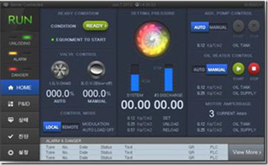
Control Screen

A simple concept of air density is cool air is more dense than warm air.  In a centrifugal compressor application where the flows and pressure are created dynamically the inlet conditions play a major role in the performance of the compressor.

Several factors play a contributing role in the performance including inlet pressure which should remain constant at your physical location.  However, the variable factors include inlet air temperature, humidity and cooling water temperature.

Lower intake air temperatures as well as cooling water temperatures usually go hand in hand.  The lower temperature air will be more dense and will result in higher free air delivery (ACFM) and also higher power consumption of the compressor.

Another factor in air density changes is the available turndown of the compressor.  Meaning the effective flow range through the use of a throttle valve or inlet guide vanes is possible.  A lower temperature inlet air will allow for a wider range of operation in the compressor thus offering a larger amount of turndown.

The lower inlet temperature air also increase the surge pressure!

During the heat of summer the alternate is true where less volume is produced by the compressor and subsequently, less horsepower is used but there may exist an circumstance that the unit will not be able to produce the required plant volume if the unit was not sized appropriately at the onset.

All of this information is critical in initially sizing a dynamic compressors but the point we’re looking to make is the ambient conditions do change the performance of the machine. 

Modern controls are designed to keep the compressor out of surge or choke conditions by moving the surge line to an acceptable position.  However, by moving the surge line the performance of the unit is also altered.

This is the primary reason we suggest re-tuning each centrifugal compressor based on the season.  At least twice per year (as the ambient temperatures increase for summer and decrease for winter) is an ideal time to tune the compressor to achieve peak performance and maximize energy savings.

If your plant has a maintenance contract with a service provider, make sure that tuning the compressor is included twice per year as recommended.  If you perform you own service I would advise contacting a local service company to perform these tuning parameters for your as a one off service.  Typically, tuning controls is outside the expertise of plant maintenance personnel.

Get in Touch

Controls

We’ve progressed through the components of a centrifugal compressor.  While the goal is to supply the plant with oil free compressed air, the ideal conditions of supply and demand rarely, if ever, match up.  Meaning the plant use is never matched with the exact output of the compressor.

For that reason a controller is implemented to match the output of the compressor with the needs of the plant.  The controller is responsible for monitoring all of the instrumentation on the compressor such as vibration probes, oil pressure, oil temperature, air temperature both entering the compressor as well as the temperature at the different stages.  This is to assure proper cooling is taking place in the intercoolers.  The controller also typically monitors the pressures at the discharge of each stage to assure the unit is operating at the design point and also measures the motor current.

Turndown

Another important term to understand in the centrifugal compressor world is turndown.  Basically, turndown is the operating range of the compressor between the lines of surge and choke.

image


This gives the end user an understanding of the operating range of the compressor which assists in understanding the efficiency of the unit.  Since the requirements of the plant rarely match the exact output of the compressor we need to know how much the compressors can effectively throttle back to match the plant air requirements.

Control Mode

The controller may normally be set up to control in several different scenario’s.

Constant Pressure:

Constant pressure control is frequently used when system air pressure must be held steady at a specific value or in processes where swings in system pressure is not acceptable.  The inlet valve is modulated to meet the system pressure set point while holding motor current within the Max/Min set points.  In a case of low demand, the compressor will throttle back to the surge control set point.  If demand continues to fall below these set points, the discharge (blowoff) valve will open (modulating if capable) to bypass enough flow to keep the compressor from reaching a surge condition.

Constant Flow

Constant flow control provides a constant flow delivered from the compressor to the system in special applications and works much the way constant pressure controls work.

Auto Dual

Auto Dual control provides efficient compressor operations where some pressure swings are acceptable to the plant.  In Auto Dual mode the compressor controls operate the same as constant pressure until the compressor throttles back to surge control set point.  If demand falls below the throttled condition the controller will unload the compressor.  If the plant requirements increase the compressor will reload to supply air to the plant.  On some models, if the demand remains below this threshold for a set period of time the compressor can be programmed to shutdown and auto restart when system demand requirements rise.

Efficiency Note

The controller for the compressor has a primary function of assuring the compressor meets the demand of the plant air system requirements.  Secondarily, the controller should operate the compressor at peak efficiency in order to keep electrical operating cost to a minimum.  Any time the discharge (blowoff) valve is open, expensive compressed air is being blown off to the atmosphere.  After paying to compressor the air, blowing it to atmosphere is a tremendous waste of resources. 

While most manufacturers offer a variety of interconnected local controllers, Most of these controllers simply do not have the computational power to fully utilize the compressor at peak efficiency.  Regardless of control methods, sophisticated algorithms in central control systems offer faster monitoring & control while utilizing more sophisticated programs.  An example would be where the master controller monitors the rate the system pressure falls to determine the likely time expectancy that the unit will need to reload.

For maximum efficiency it is always recommended to hire a professional compressed air auditing group that maintain engineering personnel dedicated to control systems.

Get in Touch

Do You Have a Matched System

Supply & Demand sides updated

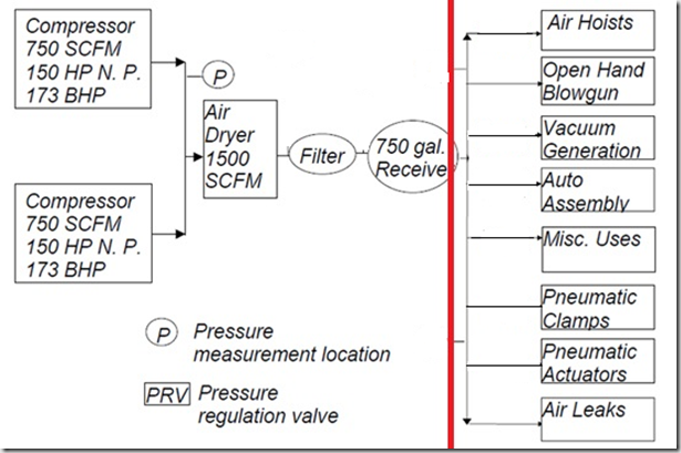
Simply put, does the drawing left of the red line (Supply) match the right side (Demand) in terms of air flow and pressure? Does it continually match? Likely it does not as demand is in constant fluctuation whether from changes in use, shift change or downtime.

Within a compressed air system, the system dynamics (changes in demand over time) are especially important. Using controls, storage, and demand management to effectively design a system that meets peak requirements but also operates efficiently at part-load is key to a high performance compressed air system.

In many systems, compressor controls are not coordinated to meet the demand requirements, which can result in compressors operating in conflict with each other, short-cycling, or blowing off are all signs of inefficient system operation.

As in most relationships, the key is communication.  Communication between the compressors so that each (or a central controller) knows the status of all the other units.  Communication is also key between the compressors (or central controller) and the demand side of the system.  The compressors perform based on information from a pressure sensor located downstream of the compressor discharge.  But where is this sensor located?

A common mistake is the pressure sensor is located close to the compressor discharge.  Perhaps even before the dryer.  If this is the case in our system drawing above, you can see that the compressor is performing based on pressure data before the air enters the dryer or the subsequent filter, both of which have pressure drop as air passes through.  This drop can range from 5 PSIG up to 12 PSIG or higher depending on how well the system was designed as well as the condition of the filter element.  A dirty element near the end of it’s life will have substantially more pressure differential than a clean filter element.

If the compressors are discharging at 100 PSIG and there is a 10 pound drop through the dryer and filter, then the plant is only receiving 90 PSIG and this doesn’t include the pressure drop throughout the plant piping system.  When a cyclical event occurs, such as several blow guns operating at the same time, the pressure drop has to travel back through the entire system before the compressors see the event and can respond to correct the drop in pressure by increasing their output.

All factors must be considered when designing or updating a compressed air system.  Your best course of action is to consult with a compressed air professional to assist in your design or upgrades prior to writing any equipment specifications.

Get in Touch

Compressor 1, Compressor 2, Compressor 3…You Get The Idea

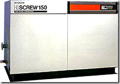
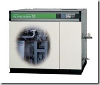
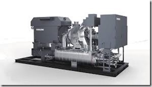
Hitachi 3745126_2stagebHitachiDSP55aSamsung Compressor


With a room full of compressors, how do you keep them all playing together nicely? Central controls is the key to an energy efficient system with multiple compressor. Even with various types and brands a central control system can form a chain of command that keeps the plant satisfied while reducing energy costs.

The simplest central control is utilizing the existing compressor controllers for communication between the compressors allowing one or two units to focus as the lead machine and calling on the remaining compressors to assist in high load conditions. This could be by automatically loading or modulating one or several of the remaining units.

System master controls have many functional capabilities, including the ability to monitor and control all components in the system as well as trending data to enhance maintenance functions and minimize costs of operation.

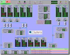
What if your compressors are from multiple manufacturers and the controllers will not communicate with each other? Time to call on an outside source such as IZ Systems. The IZ Systems central control system can communicate with all compressor manufacturers controls and allow many enhanced functions not usually associated with normal compressor controls such as web based control, real time energy consumption and even contracts allowing our specialist to monitor your compressed air components for you remotely, giving you piece of mind 24/7/365.

Get in Touch

Control Your Compressed Air


Compressed Air Controls

Improving and maintaining compressed air system performance requires not only addressing individual components, but also analyzing both the supply and demand sides of the system and how they interact, especially during periods of peak demand. This practice is often referred to as taking a systems approach because the focus is shifted away from components to total system performance.

Latest edition controllers from both the OEM and aftermarket suppliers offer the most sophisticated algorithms for unit control and incorporate sensitive digital sensing devices which all combine to give you the most efficient and reliable control.  The better control you have of your compressor allows operators to select the lowest possible operating pressure allowing the plant to save significant money on operations and maintenance costs.  Almost all of these controllers offer remote monitoring and remote control where operators are not required to be standing by in the compressor area to monitor data points or select update operating methods.

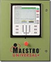
Universal Controller 50               Bay Controls

Controls from IZ Systems offer a complete compressor control automation package capable of handling any type of compressor, dryer, cooling tower or chiller system.  Thus allowing integrated control of the entire system which further reduces the operations cost and further improves reliability.

IZ Controller

Get in Touch

Can Your Air Compressor Make Phone Calls

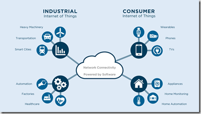
I read an article (link below) Sunday night from “Plant Services” discussing how the IIoT is coming to compressed air.  If you’re not familiar with IIoT, it’s the industrial version of the IoT.  In case you’ve not heard of IoT, let me give you a quick explanation.  IoT stands for the “Internet of Things” and subsequently, IIoT stands for the “Industrial Internet of Things”.

Industrial-Internet-of-things

The premise of IoT is that you and your entire home can be connected with all the components and subsystems being able to communicate and interact with each other.  Basically, a Smart Home.  What drives me crazy is that the authors of these articles promote this is new.  This is NOT NEW!  My house has been automated for over 20 years.  The lighting, HVAC, security system, garage doors, home theater, whole house sound system along with others all respond to the central computer that controls it all and can be activated by buttons on my iPhone, keypads in the house or timed based controls.  It doesn’t need access to the internet, nor do I want it connected to the internet.  One less thing I have to be concerned with related to viruses and hacking.  Sure a connection to the internet could add a few features to my system but it’s not worth the worry at this point.

IoT_edited

Now on the article in “Plant Services” discussing IIoT and how its coming to compressed air equipment.  It states how compressed air equipment utilizing IIoT and connecting to the internet will be “a game changer based on the energy-saving impact”.  It further states “it will bring smarter control for better efficiency and easier compliance reporting”.  My question is: compliance to what and reporting to who?

The goal of any compressed air system in today’s world is better efficiency but you certainly do not need an internet connection for that to happen.  My vendor for central compressed air system control (IZ Systems) has been providing this capability for years.  Maybe not as long as my house has been automated but for a lot of years.  The current system doesn’t require changes to the local controls and can be tied into nearly any type or brand of compressed air equipment.  Thus making the system reliable as any failure in the central system will revert control back to the local controller.

The key to energy efficiency has nothing to do with the internet but rather with the central processor that controls the compressed air equipment while monitoring the entire compressed air system and more importantly, the proprietary algorithm that resides in the central processor.  Yes, they can use an internet connection to remotely monitor the system but this plays no part in the efficiency and in fact, many of my existing clients will not allow their equipment to access an internet connection due to the same concerns I have over my house.  Additional security concerns.  The benefits just don’t outweigh the potential headaches.

But, the article states, with the IIoT, my compressor can call the service technician if there is a potential problem.  I’m sure this would save all my clients some time however most of my clients already tie equipment monitoring into their DCS and trend various data points such as temperature, pressure and vibration.  If there is an escalating problem the DCS notifies them and they determine who needs to be called for further inspection or repair.  So in my opinion, having your air compressor make phone calls is not going to add a lot of hours to your day.

Rather than waiting and hoping the IIoT progresses to a usable point, in my opinion, your money would be better spent investing today in a solid service contract with a company that can provide true vibration analysis.  I’m not talking about trending but rather vibration analysis by professionals that know what the frequency’s should be on your equipment and can spot problems from one initial vibration analysis.

I think you can determine that I’m no luddite.  In fact, quite the opposite.  I love technology and the great things it can provide us.  I just don’t want my clients getting caught up in the wave of hype surrounding a supposed new technology and spending money on features that are either easily available today or worse, for something they don’t really need.

Perhaps as the IIoT progresses I’ll be proven wrong and this technology can truly provide value to my clients.  But for today, I see it as a half baked cookie that nobody really needs to bite into.

Here is a link to the original article if you’re interested.

Get in Touch

Point Of Use Compressed Air Storage

Air Receiver

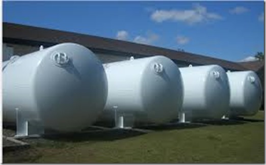
There are frequent articles on the site touting the benefits of compressed air storage.  We usually refer to large receiver tanks as the ones pictured above.  This article will focus on the benefits of local storage or receivers located at or near the point of use where there are one of just a few intermittent high flow demands.  I have found this technique to be extremely beneficial in bag house pulsing applications.

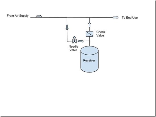
A correctly-sized storage receiver close to the point of the intermittent demand with a check valve and a metering valve can be an effective and lower cost alternative. For this type of storage strategy, a check valve and a tapered plug or needle valve are installed upstream of the receiver. The check valve will maintain receiver pressure at the maximum system pressure and only allow air to be consumed from the receiver when the system line pressure falls below the pressure of the receiver.  The plug or needle valve will meter the flow of compressed air to “slow fill” the receiver during the interval between demand events. This will have the effect of reducing the large intermittent requirement into a much smaller average demand.

full_776a4e4e-5e29-4da1-b49a-edcaf2f30c6b-Point_of_Use_Storage


Get in Touch

Utilizing Compressed Air Storage

If you look at most any industrial compressed air system you will find a receiver located somewhere in the layout. However, just having a receiver does not mean the system is fully utilizing the capability of the storage.

Air Receiver


Properly utilized compressed air storage should allow a compressed air system to meet its peak demand needs and help control system pressure without starting additional compressors. The correct type and quantity of air storage depends on air demand patterns, air quantity and quality required, and the compressor and type of controls being used. An optimal air storage strategy will enable a compressed air system to provide enough air to satisfy temporary air demand events while minimizing compressor use and pressure.

To properly utilize the stored compressed air the pressure in the receiver needs to be stored at a higher pressure than the system pressure. The strategy is to allow the differential between these 2 pressures to be sustained by incorporating a pressure flow controller (PFC) and/or metering valves.

This allows the pressure in the demand side to be reduced to a stable level that minimizes actual compressed air consumption. PFCs are added after the primary receiver to maintain a reduced and relatively constant system pressure at points of use, while allowing the compressor controls to function in the most efficient control mode and discharge pressure range. Properly applied, a PFC can yield significant energy savings in a system with a variable demand load.

A professional air audit can determine the proper storage size requirements.

Get-in-Touch.png