Don’t Restrict The Flow

image

It seems most every plant I visit has a low pressure problem somewhere in the plant.  I’ve written before discussing how pressure flow controllers (PFC) can help with low pressure it certain situations but today I wanted to look at a more common problem.  Inadequate pipe size can be a major contributor to low pressure problems in the plant.

Physics dictates that only a certain amount of product, whether it be compressed air, gas or water, will flow through a certain diameter pipe.  Also, regardless of the flow being moved the friction of movement causes pressure drop.  The more flow that’s attempted to be pushed through the pipe the higher the pressure loss.

I typically see the problem where a plant started with good intentions and design practices but as the plant expands, the main headers and subsequent drop lines are still being used from the original plant air piping system.  There is also the case where the original piping was just not large enough to accommodate the flow and the problem gets progressively worse as the years go by.

An often used fix for the problem is to simply set the discharge pressure on the compressor to a higher level which for a period of time will result in a higher pressure reaching the use point.  However, as we’ve previously discussed, this solution costs money.  Lot’s of money!  Therefore the maximum pressure drop should be limited to approximately 1 1/2 PSI between the compressed air system discharge (outlet of the last filter) to the point of use.

The size of the pipe is not the only contributing factor in the plant.  Every item within the piping system also plays a very important factor.  Consider that each bend (45 or 90 degree) also adds to the limit of the flow through the pipe as well couplings, flex hoses, and quick connects.  When all the restrictions are added up it can amaze the end user just how much restriction is in the piping distribution system.

When reviewing the piping system the following items must be taken into account:

  • Diameter of pipe
  • Length of pipe
  • Number of bends couplings (other restrictions)
  • SCFM of air required to be passed.

First ,determine the flow from the compressor.  This should be a standard rating given by the manufacturer usually in SCFM or Standard Cubic Feet per Minute at a given pressure.  It’s wise to note that the SCFM rating by the manufacturer is the flow the compressor can deliver at a standard condition.  Meaning the compressor will deliver a given SCFM of air at 68 degree F and 20% relative humidity and if you are reviewing a dynamic compressor, the elevation is also taken into consideration.  When any of these parameters are changed then the delivered air by the compressor changes as well. 

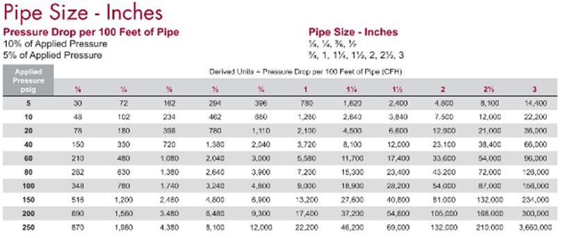
Next, review the chart below, finding your pressure rating in the left hand column and matching it to the pipe size being considered from the top row.  The intersection point of these two data items shows the amount of air that can be delivered through the pipe with the stated pressure drop.

Industrial Gas Catalog 2009.indd


Also, remember that the table shows information for straight pipe runs.  It does not take bends, couplings, tee’s or other restrictions into account.  A pipe with one 90 degree bend will have a greater pressure drop than a straight run of pipe.  If the pipe run has 1 bend and 1 tee then the pressure drop will be even higher.  The simplest way to add these restrictions to the calculations is to use “equivalent pipe lengths”

The table below shows elbows, Tees, Returns and valves for various size pipe.  Adding one of these items equals adding a certain length of pipe to your piping system.  For example: adding 1 long radius 90 degree elbow to a 3″ pipe would add a restriction to your piping system that equals 3.4 feet of additional pipe which can be added to the total pipe length in the table above.

Equivalent Pipe Length Table

Knowing the flow capacity of your compressed air piping distribution system is a critical aspect to achieve maximum efficiency for your system.  The slightest change can create a major end result when you’re dealing with thousands of feet of pipe.  Even the type of pipe and connections make a difference in flow restrictions. 

For new systems where the number of restrictions is unknown, a general rule of thumb is to multiple the total estimated pipe length by 5.5 to estimate for bends, couplings and valves.

When in doubt, it’s always best to consult your compressed air professional for assistance.


Get in Touch

Drain The Water

Todays topic is automatic drain valves.  We’ve discussed hot weather, cooling water temperatures and air dryers over the past several weeks.  Regardless of how cold your cooling water is or how clean you’ve kept your air compressors and coolers, all of your efforts are in vain if you don’t get the condensed water out of the system.  Enter the automatic drain valve!

Drain valves come in a variety of configurations but they all attempt to perform the same task.  Once you have condensed the water vapor that has infiltrated your compressed air into a liquid form, the water then has to be removed from the system.  Coolers have a separator that removes the water from the air, filters remove the water from the air which then ends up in a collection area of the filter housing and depending on the location, water can also collect in air receivers.  The collection area of each device will normally have a valve that can be opened to drain the collected water and direct it to a sewer or holding area.

However, most companies will not pay a maintenance tech to stand at each collection point to open the valve to drain the water so automatic drains are installed at these areas.  It is crucial to keep these drains in top operating condition as when the auto drain fails the collection area of the separator, filter or air receiver fills with water.  At this point additional water that is condensed has no place to go except downstream which is the exact problem we’re trying to eliminate.

Prior to discussing the various types of drains, it is vital to note that when using lubricated compressors the condensate that is discharged will also contain trace amounts (hopefully just trace amounts) of compressor lubricating oil.  Nearly all municipalities frown highly on this oil reaching their water treatment systems and large fines may be imposed if this occurs.  While we are experts in oil free air, many readers of my blog do incorporate oil lubricated compressors which is the reason for my cautionary statement.  For lubricated compressed air systems the use of oil/water separators is highly recommended to remove any lubricant from the water prior to discharge.

Timed Solenoid Automatic Drain Valves

Solenoid drain

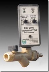
The timed solenoid auto drain has been around for many years and has been used in a variety of applications.  The operation is simple in that the solenoid triggers at timed intervals which allows the valve to open.  You will note on the photo that there is a dial to allow the timing of the valve to be adjusted.  So for high water loads the valve can be set to actuate every minute or if the water loads are low you can extend the operation to only occur once every 45 minutes.  The actual range on the unit shown is 1 minute to 60 minutes.  Looking a the photo above you will also note a second dial which modifies the duration of the cycle.  This allows a specific time that the valve will remain open each time it actuates.  For example the valve can be set to actuate every 5 minutes and remain open for 10 seconds or any combination the user selects.  The actual duration of the valve pictured can be set between 1 to 60 seconds.

This valve is often incorporated into systems because of the inexpensive cost to purchase but as with most inexpensive solutions there are hidden cost to consider.  When this valve actuates, not only is water discharged but also compressed air that we have just spent money for the compressor to compress.  Now we simply vent this expensive compressed air to the atmosphere where the benefit is lost.  These valves typically operate on 110 volts and while the electric use is slight there is still an expense.  One of the most important items to note is the valve, since solenoid actuated, has a very small opening.  While the main valve seen above looks to have rather large openings of 1/4″ to 1/2″ the actual opening in the valve is quite small.  On this particular unit the manufacturer specifies a healthy 5/32” orifice size.  The small opening lends itself to contamination plugging the valve.  The valve must then be cleaned and worse, is not operating to remove the water from the system until someone notices there is a problem.

Full Port Ball Valve Drain

DRAINMASTER® Timed Automatic Drain Valve

The full port ball valve drain was introduced to eliminate the clogging problems associated with the solenoid type drain valves.  This valve type is available from 1/2″ to 1 1/4″ with a full port ball valve that is rotated to open and continue the cycle to close the valve.  These units typically incorporate a powerful motor capable of driving the ball past any debris that might collect and are therefore very reliable.  The operation of this unit is based on a time schedule set by the user.  This type of drain is consuming electricity to operate and also discharges valuable compressed air while purging the condensate.  As expected, the ball valve type drain has a higher initial investment than the previously discussed solenoid type drain but vastly increases reliability.

Zero Loss Automatic Drain Valve

dehydra 52

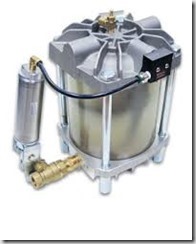
The premier drain valve is one that actuates when it senses there is enough water in the system that needs to be evacuated, uses no electricity, is reliable and does not expel valuable compressed air with the condensate.  Enter the zero loss type automatic drain.  These drains are pneumatically operated and  require no electricity so installation is simple.  They offer a full ported ball valve which eliminates clogging and offers rapid discharge of the collected condensate.  With this type of unit, the condensed water is gravity fed to the large collection chamber built into the drain rather than sitting unseen somewhere in a separator, cooler or filter within the system.  The translucent collection chamber offers a visual indicator of the collected water making it simple to verify the unit is working and most units also incorporate a test button to easily check the unit operation.  The key feature for this type of drain is that NO compressed air is lost during the purge cycle!

Unit Operation

Condensate enters the drain through one of two inlet connections. A non-metallic float is tethered to a float arm. As condensate is collected and the translucent reservoir fills, the float rises. When the condensate reaches a design level, the float lifts the trigger assembly and a drain cycle is initiated. The trigger assembly opens and directs control air to the valve actuator, which in turn opens the full-port drain valve.  While the drain is open the inlet is blocked to keep all of the compressed air contained for use within the system.

Condensate will then exit the unit. As the condensate level drops, the trigger assembly closes and the valve actuator closes the drain valve. The drain is returned to a standby condition.

Obviously the premier product also carries a premier price.  The zero air loss drains are substantially more expensive than solenoid or ball valve drains but offer a quick ROI based on zero compressed air loss, no electricity consumption and increased reliability.

A word of caution: The above pictured unit is a Dehydra 52 by Air System Products.  Reading the unit operation paragraph above it is important to note the the float is non-metallic.  Other manufacturers uses metal floats and a magnet to facilitate the drain cycle.  These units have been known to fail when metal particles (pipe scale) enter the system and attach to the magnet thus decreasing the holding capacity of the magnet to hold the float in place during the drain cycle.


Get-in-Touch-5