Cool The Air

We’ve discussed how the air is compressed through each component in a centrifugal compressor.  Now that the air/gas has been compressed in the 1st stage, it has an elevated temperature.  An example on a 400 HP machine with the air inlet temperature at 75 degrees F. the air temperature as it exits the 1st stage is approximately 242 degrees F.

As previously discussed, the ability of the compressor to meet the required performance is based on inlet pressure, inlet temperature and humidity levels.  With cooler air being more dense it is also more easily compressed.  Since the air leaving our 1st stage is at 242 degrees, we need to cool the air down before we move it to the 2nd stage of compression.

Enter the cooler, the next component of discussion in our centrifugal compressor.  Unless, there is a very specialized application the manufacturer will supply a cooler between each stage of compression and a final cooler (after-cooler) after the final stage of compression to cool the air prior to the next stage of compression or enter the plant distribution system.

Normally on compressors as large as centrifugals the cooling medium will be water although some manufacturers do provide air to air coolers up to certain horsepower machines.

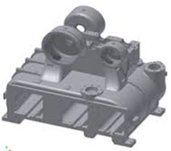
imgres

The photo above is a fairly normal centrifugal compressor gearbox and cooler casting.  This is the base building block of the compressor.  The 3 square holes near the bottom of the casting is where the 2 intercoolers and single aftercooler will be located.  the circular holes toward the top are where the impellers and diffusers will reside and the scroll will be mounted to the outside of the circular holes once the impeller and diffuser are mounted.

Remember I stated this is a fairly typical gearbox/cooler casting.  Manufacturers will incorporate a single casting design which can be utilized for several HP sizes.  This saves the manufacturer money rather then a casting design for each single HP compressors. 

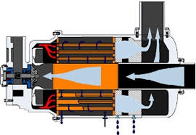
Other designs can be found as well.  One design is shown below where the cooler or cooling tubes surround the inlet air path.  As you can see the air is being drawn down the center toward the impeller.  The air exits the impeller/diffuser to each side where it then channels back through the cooler.  The main issue with this design is the difficulty in disassembly to make any repairs unlike the casting design shown above where the coolers can be independently & easily removed.

images(1)

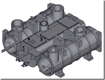
Best in class design can accomplish even more.  You can see in the photos below that certain manufacturers create separate gearbox and cooler housing castings.  The thought process here is that the gearbox can still be usable for a range of HP sizes but the cooler sizing type can also be customized.  By bolting the gearbox casting to the  cooler casting you complete the casting assembly.  In the event a client needs special large or smaller coolers or perhaps the client needs an API compressor then the gearbox casting and cooler requirements can be totally customized.

ImageImage(1)

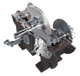
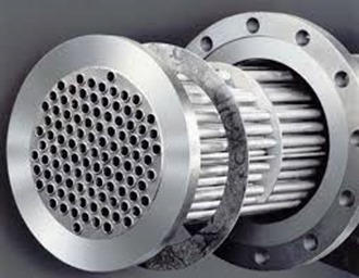
Moving on to the actual working of the cooler.  The cooler itself contains a series of tubes, the inner portion of the photo below.  Best design has the water flowing through the tubes although certain manufacturers reverse this and have air flowing through the tubes.  The air enters the shell of the cooler and flows by the tubes containing the water.  The air transfers the heat to the cooling water flowing through the tubes and the water then exits the cooler flowing back to a cooling tower, chiller or in rare cases a drain if the plant is using city water with a once through design.  (A very expensive alternate)  Most often the tubes are also surrounded by fins which aides in the heat transfer process.

images(2)

A few other items that are important to note:

The tubes in the cooler can be either straight or U-Tubes.  A straight tube design has the water entering one end of the tube, flow straight through to the other end where it exits the cooler assembly.  A U-tube design (cheaper) has the water enter one end of the tube, flows to the opposite end of the cooler where the tubes bends 90 degrees and flows the water back to the originating end of the cooler where it exits.  A U-tube cooler can only be chemically cleaned!  A straight tube design offers the ability to remove both end caps and be mechanically rodded for cleaning.  Please allocate the extra money (if required) and specify straight tube coolers!

The tubes and fins can be made of special materials depending on the service of the machine.  Normal material of construction is copper tubes and aluminum fins.

You will normally hear of coolers being rated in approach temperature such as a 10 degree approach or a 15 degree approach.  This simply means that the air leaving the cooler will be X degrees higher than the cooling medium – in our case normally water.  Where X is the approach rating.  So if a cooler is rated at a 10 degree approach and we have 80 degree water, the air leaving the cooler will be 90 degrees.

So now we’ve cooled the air down to an acceptable temperature for use in the next phase – either the next stage of compression or plant use.

If you read my dryer series you might remember when you have hot air and then cool it down you also condense water.  The same thing just happened in the inter or after cooler.  We had hot air (which is capable of holding large amounts of water vapor) and cooled it down so the water vapor condenses changing it to a liquid state.  Now we certainly do not want liquid water going downstream to our plant and we REALLY do not want liquid water going into our next impeller!  Therefore the design of the cooler casting must be such that the liquid water drops out of the air stream to a low collection point where an automatic drain valve will disperse the water to a drain outside the cooler casting.

A final note on condensate.  We’re discussing water & metals which equals corrosion over a period of time.  Air passages can be sprayed with an anti-corrosion coating for additional protection.  Some manufacturers charge extra for this item and some provide it as standard.  Yes, coating also wear away but any additional protection from corrosion is a good thing!  Remember, your impellers are spinning at high speeds (up to 100, 000 RPM) with very close tolerances.  A piece of rust slag hitting an impeller is not a good idea!

Get in Touch

Rise & Collect

We’ve previously discussed that high velocity air leaving the impeller impacts the blades on the diffuser which slows the air which causes the air pressure to rise.  The next component in a centrifugal compressor is the scroll. Sometimes referred to as the volute.

Scroll 1

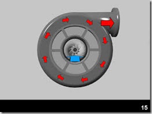
Once the air passes through the diffuser blades it enters the scroll.  As you can see in the above picture, the air passes around the scroll and exits at the top right discharge port.  The air passing through the scroll is further reduced in velocity in which again causes a rise in pressure.

At this point the first stage of compression is finalized resulting in the final pressure from the 1st stage of compression which typically results in a discharge pressure of approximately 14 PSIG on a 100 pound compressor design.  Remember, the aerodynamic engineer can alter the various aspects of the impeller, diffuser and scroll to achieve various outcomes.

It’s also important to note that we likely started with an inlet pressure to the compressor at approximately 14.3 PSIA.  The absolute atmospheric pressure at the location of the compressor.  This location and subsequent absolute pressure are critical considerations for the compressor.  A machine designed for installation at the beach (sea level) with an absolute pressure of 14.7 will not have the same performance if it is moved to a mountain in Denver with an atmospheric pressure of 12 PSIA.

Always assure you’re using the correct readings, whether PSIG or PSIA.  Gauge pressure vs. absolute pressure makes a huge difference.  It’s also interesting to note that most of the work related to pressure increase on a centrifugal compressor is done in subsequent stages.

The secondary function of the scroll is to provide a smooth collection of the air where it will be passed to the next section of the compressor.  The next section could be discharge to the plant, discharge to the next stage of compression or most commonly to a cooler.


Get in Touch

Slow The Air Down–Raise The Pressure

We previously discussed how to get the air moving and the role of the impeller in a centrifugal air compressor.  Now that we have air moving at a high rate of speed we need to slow it down.  Slow it down?  Speed up, Slow down – sounds like old people driving on Sunday morning!

I went in search of a great description for today’s topic, the diffuser.  Below is an excerpt from Wikipedia:

As the flow continues into and through the centrifugal impeller, the impeller forces the flow to spin faster and faster. According to a form of Euler‘s fluid dynamics equation, known as pump and turbine equation, the energy input to the fluid is proportional to the flow’s local spinning velocity multiplied by the local impeller tangential velocity.

In many cases the flow leaving centrifugal impeller is near the speed of sound (340 metres/second). The flow then typically flows through a stationary compressor causing it to decelerate. These stationary compressors are actually static guide vanes where energy transformation takes place. As described in Bernoulli’s principle, this reduction in velocity causes the pressure to rise leading to a compressed fluid.

What?

I’m glad you’ve made it to this point.  I’m sure you’re thinking, “Principles & Equations, I just want to know how a centrifugal compressor works?”

Here goes: The next piece of the centrifugal compressor is the diffuser.

Diffuser 1

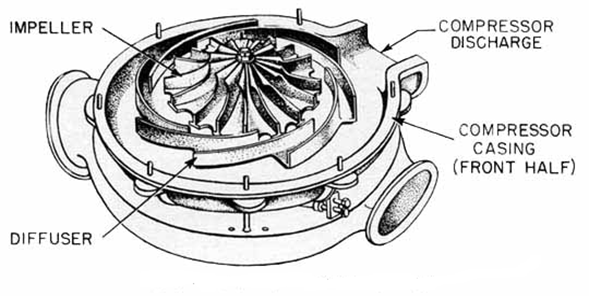
The air leaving the tips of the spinning impeller at high speed now impacts on the stationary diffuser to slow the air down.  By slowing the velocity of the air, a rise in pressure is created.  

Impeller-Diffuser

Imagine a car hitting a wall.  Until reaching the wall the car moving with only slight resistance from atmospheric air.  Note that there is some slight pressure against the car at this point which will be important for later discussion’s.  But once it hits the wall the pressure is increased and the increase in pressure collapses the metal of the car.


images

Same thing when the high speed air hits the diffuser.  An increase in pressure, which is what we’re really looking for – compressed air.

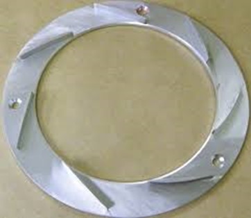
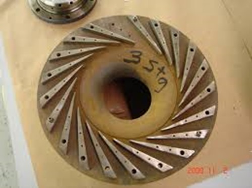
Notice the diffuser below is not just a plain wall.  It has blades on the surface as well.  We don’t really want the air to completely stop (like a car hitting a wall).  We just want to slow it down a bit so the pressure will increase.

Diffuser 3

If you recall discussing the impeller, aerodynamic engineers determine the speed of the impeller along with the length and depth of the impeller blades so the air is moving at the desired velocity.  The same is true with the diffuser.  The engineer determines the number, length and depth of the blades on the diffuser to slow the high speed air to the pre-determined amount to get just the right amount of pressure rise while maintaining the desired flow of air to the next component of the compressor.


Get in Touch

Centrifugal Compressor: Moving The Air

A recent blog post discussed a presentation to a valued client on the topic of centrifugal compressor components, operation, maintenance and troubleshooting.  This client owns and operates 20+ centrifugal compressors ranging from 1000 to 5000 horsepower.  We were surprised to see the number of attendees to the class.  Our thought process was with the number of compressors at this facility, everyone knew everything about centrifugal compressors.  We were wrong.  So you don’t misunderstand, there are lots of capable personnel at the facility but with the constant turnover of position changes, promotions and general churn,  there were plenty that were looking for education.

I surmised that if this plant could use some refresher, then a lot of other people would likely be looking for information as well.  For the next few weeks I’ll be covering some of the items from that presentation.

The photo below is the basic component of a centrifugal compressor: The impeller or often called the wheel.

The wheel is the primary rotating component that moves the air.  

Image

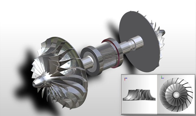
The wheel is mounted on the pinion which lies horizontally in the compressor.  You’ll note that the pinion below has two impellers, one on each end.  This is a common configuration although it is equally common to have only one impeller on a pinion.  

The air enters the impeller at the small end and the vanes grab the air and accelerate it through the vanes to the larger end where it is basically thrown from the fins.  The increasing velocity of the air is the beginning point of how the pressure is increased in a centrifugal compressor.

ImageImpeller Low Profile

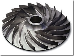
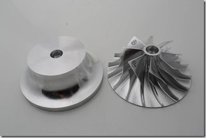
Notice the variation of the blades of the impeller from the two photos above.  The bottom picture shows a much shallower blade as well as the blade being shorter.  The depth, length and angle of the impeller blades is one of the keys to how the aerodynamic engineers achieve various performance from the unit.  The material strength and amount of material is also critical as these impellers can turn up to 70,000 RPM and higher.  Obviously, at these speeds you certainly do not want a blade breaking off which would complete wreck the compressor.

In todays modern engineering and machining world, these impellers are typically cut from a blank stock piece of material using a 5 axis milling machine to achieve the precise characteristics the engineer has determined is required to meet the  performance requested by the end user.  ie: a given flow (ICFM) at a given pressure.   Some manufacturers will create impellers by a casting or forging process although these will result in a less sophisticated component.  The design of the impeller is two-fold, in that it achieves the flow & pressure characteristics required while offer the optimum efficiency for the compressor’s energy requirements.  Again, this is where the best of engineering design creates the most reliable and efficient compressor.

Impeller Blank

The stock material can be of carbon steel, stainless steel or in certain cases, exotic materials depending on the particular gas the unit will be compressing.  Top rated centrifugal compressors for service in compressing air will use stainless steel material rather than carbon steel to achieve longer component life .

Get in Touch

More From Fluid Energy

Last week I announced the new best centrifugal compressor available from Fluid Energy.  This week I want to bring even more from our product line additions. 

Fluid Energy has always been the premier source for centrifugal compressor applications but we want to offer even more.  Being the foremost source for centrifugal compressors allows us a position to help a great number of clients.  Our only apprehension was there remained a great number of clients with smaller oil free compressed requirements that we simply could not assist.  These smaller applications called for a different technology utilizing oil free screw or oil-less scroll compressors.  Over the years Fluid Energy has been approached by a number of manufacturers looking for premier representation of their product line.  Unfortunately, none of these manufacturers met the exacting standards that the Fluid Energy team requires from the products it represents.

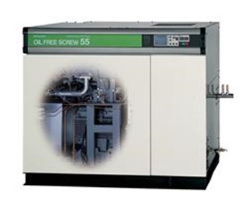
HitachiDSP55a

That Changes Now!

Our distribution agreement with Hitachi positions Fluid Energy to cover ALL of your oil-free compressed air requirements.  Hitachi, being the world leader in oil-free rotary screw  and oil-less scroll compressor technology, lets us assist facilities previously left to less qualified vendors.  Now even the smallest facilities (or small applications within large accounts) can receive the Best-In-Class products and service from Fluid Energy!

The most concerning aspect of oil free rotary screw compressors is the built in failure point – rotor coatings!  With no oil in the compression chamber (air end) to act as a sealing mechanism, the rotors of an oil free rotary screw compressor require a coating to act as a seal thus allowing the intermeshing rotors to compress the air.  As the coating degrades, the efficiency of the air end diminishes and ultimately will no longer compress the air to the design point which requires a costly air end replacement.  A large competitive supplier of oil free rotary screw compressors even states in their operation manual the life expectancy of the air end at 5 years!

Features & Benefits
  • With Hitachi’s patented HX18, Teflon-free coating over their stainless steel rotors our clients can be assured that air end failures from coating degradation are a thing of the past.
  • Hitachi’s two stage air cooling system offers a  patented stainless steel high pre-cooler which eliminates the opportunity for thermal fatigue of the after cooler thus allowing increase efficiency and reliability.
  • The standard equipment “motorized isolation valve” assures moisture causing corrosion is eliminated.
  • The included mist eliminator assures no oil deposits are in the ambient air.
  • ISO class 0 certification
  • With Hitachi US headquarters located in Charlotte, NC along with Fluid Energy’s various Southeast maintenance facilities, replacement parts & service are a quick phone call away.
  • CSG: Customer Satisfaction Guarantee offers a 3 year bumper to bumper warranty including parts & labor with an optional extended air end warranty assure end users their plant will be running at peak efficiency for years to come.
  • Factory Trained and Certified service technicians.

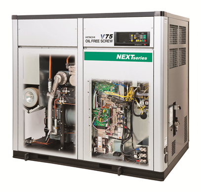
See Inside The Future

DSPV75-NEXT-skeleton (1)

See all the features in the product Video here

Oil-Less Scroll Compressor

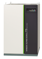
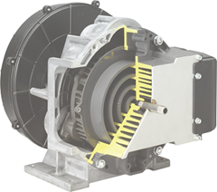
For even smaller applications the Hitachi oil-less scroll compressor is the technology to fit your requirements.  From 2.5 to 44 horsepower utilizing single & multiple head designs we can fit a compressor to your requirements up to 145 psig.  Hitachi actually manufactures the scrolls used on their compressors while the majority of competitors purchase cheaper scroll heads and simply package them on their base.  With only two principal manufacturers of scroll type air compressor heads, wouldn’t you feel more secure knowing the manufacturer of your compressor actually understands the primary component? 

06_SRL-7.5DMPCutaway of SRL

Learn more about Hitachi’s SRL Scroll series in the product Video

Contact us today to learn more about taking your facility to the “Next” level.


Get in Touch

Don’t Restrict The Flow

image

It seems most every plant I visit has a low pressure problem somewhere in the plant.  I’ve written before discussing how pressure flow controllers (PFC) can help with low pressure it certain situations but today I wanted to look at a more common problem.  Inadequate pipe size can be a major contributor to low pressure problems in the plant.

Physics dictates that only a certain amount of product, whether it be compressed air, gas or water, will flow through a certain diameter pipe.  Also, regardless of the flow being moved the friction of movement causes pressure drop.  The more flow that’s attempted to be pushed through the pipe the higher the pressure loss.

I typically see the problem where a plant started with good intentions and design practices but as the plant expands, the main headers and subsequent drop lines are still being used from the original plant air piping system.  There is also the case where the original piping was just not large enough to accommodate the flow and the problem gets progressively worse as the years go by.

An often used fix for the problem is to simply set the discharge pressure on the compressor to a higher level which for a period of time will result in a higher pressure reaching the use point.  However, as we’ve previously discussed, this solution costs money.  Lot’s of money!  Therefore the maximum pressure drop should be limited to approximately 1 1/2 PSI between the compressed air system discharge (outlet of the last filter) to the point of use.

The size of the pipe is not the only contributing factor in the plant.  Every item within the piping system also plays a very important factor.  Consider that each bend (45 or 90 degree) also adds to the limit of the flow through the pipe as well couplings, flex hoses, and quick connects.  When all the restrictions are added up it can amaze the end user just how much restriction is in the piping distribution system.

When reviewing the piping system the following items must be taken into account:

  • Diameter of pipe
  • Length of pipe
  • Number of bends couplings (other restrictions)
  • SCFM of air required to be passed.

First ,determine the flow from the compressor.  This should be a standard rating given by the manufacturer usually in SCFM or Standard Cubic Feet per Minute at a given pressure.  It’s wise to note that the SCFM rating by the manufacturer is the flow the compressor can deliver at a standard condition.  Meaning the compressor will deliver a given SCFM of air at 68 degree F and 20% relative humidity and if you are reviewing a dynamic compressor, the elevation is also taken into consideration.  When any of these parameters are changed then the delivered air by the compressor changes as well. 

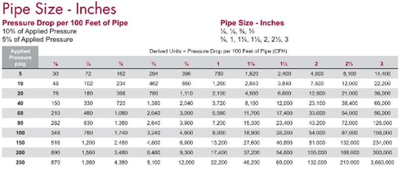
Next, review the chart below, finding your pressure rating in the left hand column and matching it to the pipe size being considered from the top row.  The intersection point of these two data items shows the amount of air that can be delivered through the pipe with the stated pressure drop.

Industrial Gas Catalog 2009.indd


Also, remember that the table shows information for straight pipe runs.  It does not take bends, couplings, tee’s or other restrictions into account.  A pipe with one 90 degree bend will have a greater pressure drop than a straight run of pipe.  If the pipe run has 1 bend and 1 tee then the pressure drop will be even higher.  The simplest way to add these restrictions to the calculations is to use “equivalent pipe lengths”

The table below shows elbows, Tees, Returns and valves for various size pipe.  Adding one of these items equals adding a certain length of pipe to your piping system.  For example: adding 1 long radius 90 degree elbow to a 3″ pipe would add a restriction to your piping system that equals 3.4 feet of additional pipe which can be added to the total pipe length in the table above.

Equivalent Pipe Length Table

Knowing the flow capacity of your compressed air piping distribution system is a critical aspect to achieve maximum efficiency for your system.  The slightest change can create a major end result when you’re dealing with thousands of feet of pipe.  Even the type of pipe and connections make a difference in flow restrictions. 

For new systems where the number of restrictions is unknown, a general rule of thumb is to multiple the total estimated pipe length by 5.5 to estimate for bends, couplings and valves.

When in doubt, it’s always best to consult your compressed air professional for assistance.


Get in Touch

Drain The Water

Todays topic is automatic drain valves.  We’ve discussed hot weather, cooling water temperatures and air dryers over the past several weeks.  Regardless of how cold your cooling water is or how clean you’ve kept your air compressors and coolers, all of your efforts are in vain if you don’t get the condensed water out of the system.  Enter the automatic drain valve!

Drain valves come in a variety of configurations but they all attempt to perform the same task.  Once you have condensed the water vapor that has infiltrated your compressed air into a liquid form, the water then has to be removed from the system.  Coolers have a separator that removes the water from the air, filters remove the water from the air which then ends up in a collection area of the filter housing and depending on the location, water can also collect in air receivers.  The collection area of each device will normally have a valve that can be opened to drain the collected water and direct it to a sewer or holding area.

However, most companies will not pay a maintenance tech to stand at each collection point to open the valve to drain the water so automatic drains are installed at these areas.  It is crucial to keep these drains in top operating condition as when the auto drain fails the collection area of the separator, filter or air receiver fills with water.  At this point additional water that is condensed has no place to go except downstream which is the exact problem we’re trying to eliminate.

Prior to discussing the various types of drains, it is vital to note that when using lubricated compressors the condensate that is discharged will also contain trace amounts (hopefully just trace amounts) of compressor lubricating oil.  Nearly all municipalities frown highly on this oil reaching their water treatment systems and large fines may be imposed if this occurs.  While we are experts in oil free air, many readers of my blog do incorporate oil lubricated compressors which is the reason for my cautionary statement.  For lubricated compressed air systems the use of oil/water separators is highly recommended to remove any lubricant from the water prior to discharge.

Timed Solenoid Automatic Drain Valves

Solenoid drain

The timed solenoid auto drain has been around for many years and has been used in a variety of applications.  The operation is simple in that the solenoid triggers at timed intervals which allows the valve to open.  You will note on the photo that there is a dial to allow the timing of the valve to be adjusted.  So for high water loads the valve can be set to actuate every minute or if the water loads are low you can extend the operation to only occur once every 45 minutes.  The actual range on the unit shown is 1 minute to 60 minutes.  Looking a the photo above you will also note a second dial which modifies the duration of the cycle.  This allows a specific time that the valve will remain open each time it actuates.  For example the valve can be set to actuate every 5 minutes and remain open for 10 seconds or any combination the user selects.  The actual duration of the valve pictured can be set between 1 to 60 seconds.

This valve is often incorporated into systems because of the inexpensive cost to purchase but as with most inexpensive solutions there are hidden cost to consider.  When this valve actuates, not only is water discharged but also compressed air that we have just spent money for the compressor to compress.  Now we simply vent this expensive compressed air to the atmosphere where the benefit is lost.  These valves typically operate on 110 volts and while the electric use is slight there is still an expense.  One of the most important items to note is the valve, since solenoid actuated, has a very small opening.  While the main valve seen above looks to have rather large openings of 1/4″ to 1/2″ the actual opening in the valve is quite small.  On this particular unit the manufacturer specifies a healthy 5/32” orifice size.  The small opening lends itself to contamination plugging the valve.  The valve must then be cleaned and worse, is not operating to remove the water from the system until someone notices there is a problem.

Full Port Ball Valve Drain

DRAINMASTER® Timed Automatic Drain Valve

The full port ball valve drain was introduced to eliminate the clogging problems associated with the solenoid type drain valves.  This valve type is available from 1/2″ to 1 1/4″ with a full port ball valve that is rotated to open and continue the cycle to close the valve.  These units typically incorporate a powerful motor capable of driving the ball past any debris that might collect and are therefore very reliable.  The operation of this unit is based on a time schedule set by the user.  This type of drain is consuming electricity to operate and also discharges valuable compressed air while purging the condensate.  As expected, the ball valve type drain has a higher initial investment than the previously discussed solenoid type drain but vastly increases reliability.

Zero Loss Automatic Drain Valve

dehydra 52

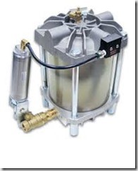
The premier drain valve is one that actuates when it senses there is enough water in the system that needs to be evacuated, uses no electricity, is reliable and does not expel valuable compressed air with the condensate.  Enter the zero loss type automatic drain.  These drains are pneumatically operated and  require no electricity so installation is simple.  They offer a full ported ball valve which eliminates clogging and offers rapid discharge of the collected condensate.  With this type of unit, the condensed water is gravity fed to the large collection chamber built into the drain rather than sitting unseen somewhere in a separator, cooler or filter within the system.  The translucent collection chamber offers a visual indicator of the collected water making it simple to verify the unit is working and most units also incorporate a test button to easily check the unit operation.  The key feature for this type of drain is that NO compressed air is lost during the purge cycle!

Unit Operation

Condensate enters the drain through one of two inlet connections. A non-metallic float is tethered to a float arm. As condensate is collected and the translucent reservoir fills, the float rises. When the condensate reaches a design level, the float lifts the trigger assembly and a drain cycle is initiated. The trigger assembly opens and directs control air to the valve actuator, which in turn opens the full-port drain valve.  While the drain is open the inlet is blocked to keep all of the compressed air contained for use within the system.

Condensate will then exit the unit. As the condensate level drops, the trigger assembly closes and the valve actuator closes the drain valve. The drain is returned to a standby condition.

Obviously the premier product also carries a premier price.  The zero air loss drains are substantially more expensive than solenoid or ball valve drains but offer a quick ROI based on zero compressed air loss, no electricity consumption and increased reliability.

A word of caution: The above pictured unit is a Dehydra 52 by Air System Products.  Reading the unit operation paragraph above it is important to note the the float is non-metallic.  Other manufacturers uses metal floats and a magnet to facilitate the drain cycle.  These units have been known to fail when metal particles (pipe scale) enter the system and attach to the magnet thus decreasing the holding capacity of the magnet to hold the float in place during the drain cycle.


Get-in-Touch-5

Keeping Cool

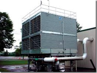
Winters icy grip is beginning to fade from memory while we enjoy the pleasant weather of spring.  We’ve not yet begin to think about the dog days of summer but now is the time to begin evaluations on your cooling towers.  Remember last summer when your air compressors could barely be kept online due to the cooling water temps.  Well, now is the time to prevent the problem from occurring again this year.

Cooling Tower


Cooling towers and fin fans are the main heat sinks at plants and any bottlenecks there show up in your process equipment.


See this great article by Riyaz Papar to get an insight on what to do before the temps are in the 90s this year.

http://bit.ly/1YU5TfG

Get in Touch